Air Conditioning System
- James Albright (a former G450 driver)
Updated: 2015-06-23
It is up to the Environmental Control System (ECS) to not only make the cabin habitable, but comfortable as well.
To do that, the air conditioning system injects comfortable air into the cabin and the pressurization system to let it out in a controlled manner. All this happens automatically in this airplane.
What follows is the air conditioning system (air in). But of course that is only half the battle. For the other half see: G450 Pressurization System.
You can go your entire G450 career without ever touching the ECS except during preflight and post-flight, it does everything for you and is very reliable. but you really should understand how the air conditioning system works.
Everything here is from the references shown below, with a few comments in an alternate color.

Figure: ECS Big Picture, (Eddie's notes)
Environmental Control System (ECS) Overview
[G450 Aircraft Operating Manual, §2A-21-10.]
The air conditioning system provides pressurized and temperature controlled airflow to maintain a comfortable environment for the occupants of the airplane and provides a source for equipment cooling.
Hot pressurized air from the compressor sections of the engines or the Auxiliary Power Unit (APU) is cooled through a series of processes by the Environmental Control System (ECS) Air Conditioning Packs (ACPs), remixed with some of high temperature bleed air to achieve the desired temperature, and then delivered throughout the airplane. Distribution ducts provide air to the cockpit, passenger cabin, and baggage compartment.
The higher pressure of this airflow allows regulation of the ambient pressure within the airplane to maintain an air density comfortable for breathing even though the airplane may be at the highest operating altitude limit of forty-five thousand (45,000) feet. Air density within the airplane is controlled by regulating how much of the pressurized conditioned air remains within the airplane. The airflow leaving the airplane is regulated by a Thrust Recovery Outflow Valve (TROV) that opens and closes in response to automatic or manual commands to maintain the desired air density level.
It is said that the air in the G450 is completely replaced every two minutes during normal operations. I don't have that in writing.
Air Flow Into the Pressure Vessel
[G450 Aircraft Operating Manual, §2A-21-20, ¶1.] Engine bleed air supplied to the ACPs is taken from the lower temperature and pressure seventh (7th) stage and/or higher temperature and pressure twelfth (12th) stage of the engine compressor. Under most operating conditions, seventh (7th) stage bleed air pressure and temperature is adequate for airplane systems operation. At low power settings, twelfth (12th) stage air may be required to meet minimum pressure and/or temperature needs. When the pressure of the twelfth stage air exceeds that of the seventh stage, a check valve closes to prevent twelfth stage bleed air from entering the engine compressor through the seventh stage.
[G450 Aircraft Operating Manual, §2A-36-20.] Temperature of the air is regulated by selective switching between compressor stages for a source of supply air and by passing the supply air through a precooler heat exchanger that uses ambient air drawn into the engine at the fan intake stage of the compressor. Pressure is controlled through regulator and shutoff valves that vary the size of the valve orifice in the manifold.
The air leaving the engine bleed air ducts has not been combusted in any way, it is just compressed. That compression heats the air over 500°F, typically. The temperature is then lowered by the pylon precooler, which uses air from the engine fan intake.
[G450 Aircraft Operating Manual, §2A-21-20, ¶1.] The bleed air in the supply manifold is controlled and regulated to forty (40) psi and four hundred degrees Fahrenheit (400°F ±10), or five hundred degrees Fahrenheit (500°F ±10) when only one engine is available for bleed air and wing anti-ice is selected ON. Engine bleed air entering the ACPs is regulated by pack inlet valves to at least fifteen (15) psi. if both engines are supplying bleed air. If only one engine is available as a bleed air source, the twelfth (12th) stage air set point of the remaining engine opens to allow at least twenty-six (26) psi.
Once the air gets to the bleed air supply manifold, it has been temperature and pressure controlled. The 40 psi and 400°F targets are only realized at high power settings, normally you will see between 15 and 40 psi and something less than 400°F.
More about this: G450 Pneumatics.
Air Conditioning

Figure: G450 ECS ACP, (G450 Maintenance Manual, §21-52-00, figure 1)
There are two air conditioning packs, one normally dedicated to the bleed air from its onside engine since the bleed air manifold is normally divided by an isolation valve. The packs are purely mechanical, using the pressure of the bleed air itself to operate all its moving parts. The pack inlet valve is electrically closed and fails open. There are multiple temperature sensors but failing all electrical power, the pack will operate.
Pack Inlet Valve
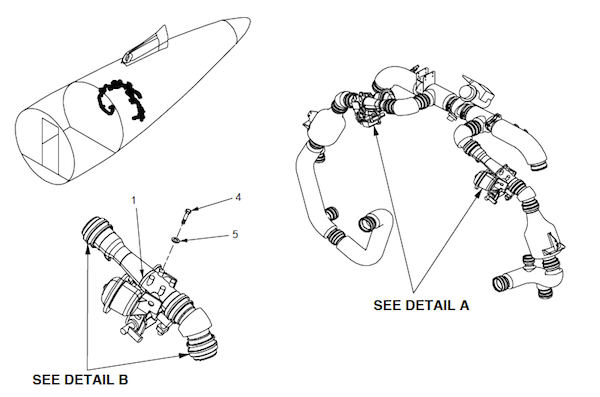
Figure: Pack inlet valves, (G450 Maintenance Manual, §21-21-01, figure 401.
[G450 Maintenance Manual, §2A-21-00, ¶3.A.] The pack inlet valve is a 2.5 inch diameter, spring-loaded-open, variable-schedule, venturi flow control and shut-off valve. Index marks indicating OPEN and CLOSED positions are provided adjacent to the actuating arm on the bracket assembly. The valve consists of a control pressure regulator, delta-P servo, servo pressure relief valve, shutoff solenoid, torque motor and actuator assembly. The shutoff solenoid responds to cockpit L/R PACK selector switch. The torque motor control valve responds to a milliampere current schedule from its respective Air Conditioning Controller (ACC). The valve schedules are as follows:
Normal Flow coincides with all normal operations with both packs operating. The ACC varies torque motor current from 85 milliamperes at sea level to 38 milliamperes at 45,000 feet. This provides equal mass flow at all altitudes.
Maximum flow is generated whenever one air conditioning pack is selected off. ACC removes all current from torque motor to provide adequate airflow from a single pack.
Minimum Flow: If an Air Cycle Machine (ACM) compressor outlet temp sensor senses 425°F (ACM max speed), the respective ACC schedules more than 90 milliamperes, positioning valve to provide 25 pounds per minute minimum airflow to maintain pressurization.
[G450 Aircraft Operating Manual, §2A-21-20, ¶1.] Indirect control of the ACPs is provided by the switches on the ENGINE START panel. If the APU is supplying bleed air for the operation of the ACPs prior to engine start, selecting the MASTER CRANK or MASTER START switch ON will shut down the right ACP. Selecting the START L ENG or START R ENG switch to ON will shut down the left ACP. The OFF legend in each pack switch will illuminate while the ACPs are not operating. The ACPs are shut down by the ACC closing the inlet valve of each ACP. When the first engine start is complete, the left ACP inlet valve will open and the left pack will return to normal operation. When the MASTER START switch is selected OFF, the right ACP will return to normal operation. This ACP automatic switching function for engine starts is confined to ground operations by the Weight-On-Wheels (WOW) switch position to preclude loss of pressurization during inflight engine starts.
The pack inlet valve requires electrical power to close so activating the cockpit switch to OFF energizes the valve closed. If all power is lost, the valve opens. In summary, the pack inlet valves will be energized closed:
If the associated pack switch is turned off.
If the RAM AIR switch is activated, both pack inlet valves close.
If the MASTER CRANK or MASTER start switches are placed ON with weight on wheels, the right pack inlet valve will close.
If the START L or START R switches are pressed with weight on wheels, the left pack inlet valve will close until the associated engine start has been completed.
Ram Air

Figure: Ram air exhaust louvers, (Eddie's aircraft)
[G450 Aircraft Operating Manual, §2A-21-20, ¶1.] Scrubbed bleed air enters the ACP, first passing over the primary stage of an air to air heat exchanger. The heat exchanger uses ambient air drawn into a ram air scoop in the dorsal fin as a cool air source to initially reduce bleed air temperature. On the ground, ambient air is drawn into the air scoop by a fan powered by the rotation of the ACP turbine (described in the following section). In flight, with high ram air pressure available from increased airspeed, most of the ram air in the inlet bypasses the fan. The ambient cooling air is exhausted through louvers in the lower tail section of the airplane.
The primary purpose of ram air is not to pressurize the cabin, it is to cool the ACP heat exchangers and it is always working whenever the pack is in operation. On the ground air is drawn into the ram air scoops on the top of the fuselage because the ACM fan is spinning. In the air, while the fan continues to spin, most of the air bypasses the fan since the aircraft's speed through the air is enough to cool the heat exchangers.
Heat Exchangers
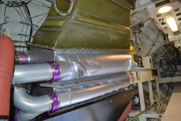
Figure: Air conditioning pack heat exchangers, right pack shown, (Eddie's aircraft)
[G450 Aircraft Operating Manual, §2A-21-20, ¶1.] After initial cooling the bleed air is routed to the compressor side of the ACP. Compressor rotation is powered by the turbine side of the ACP. Both the compressor and the inlet duct fan share a common shaft with the turbine section. The spinning motion of the compressor approximately doubles the pressure of the incoming air (in order to drive the turbine side of the ACP) and also warms the air. Some of this warm air (compressor outlet air is limited to 450°F) is ducted to the turbine side of the ACP to prevent icing in the water extraction operation of the condenser and also is used to maintain a minimum air temperature at the inlet to the ACP turbine. Most of the warmer, pressurized air is ducted through a secondary heat exchanger in the ram air duct for recooling.
Each pack has two heat exchangers, which are nothing more than large radiators which take the compressed bleed air heat to be exhausted overboard. The compressed air is then expanded, further dropping its temperature.
Water Extractors
[G450 Aircraft Operating Manual, §2A-21-20, ¶1.] The cooler pressurized air is routed for additional temperature loss and water extraction. Moisture is removed by passing the air through vanes in the condenser where the air is centrifugally spun, forcing heavier water molecules to the outside of the condenser duct where the water is separated and drained from the ACP. The air is then passed through a heat exchanger where it is warmed to vaporize any remaining moisture.
Unlike previous air conditioning packs, there is no "sock" to catch ice and under humid conditions you may hear ice shooting through the air conditioning ducts. The water extractor simply puts a spin on the air in hopes the water will swirl to the outside of the extractor where it is shot into the ram air duct. On an especially humid day, running off the APU on the ground, you can hear ice being shot through the ducts.
Air Distribution
Cold Air Manifold
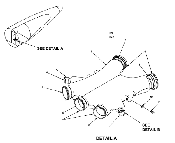
Figure: Cold air manifold, (G450 Maintenance Manual, §21-21-05, figure 302)
[G450 Aircraft Operating Manual, §2A-21-20, ¶1.] The modulated ACP airflow of both packs enters into a common cold air manifold for distribution to the airplane interior. The cold air manifold is paired with a hot air manifold to provide sources of supply for mixing air of different temperatures to achieve a desired comfort level in the cabin and cockpit.
The cold air manifold takes the conditioned air from both packs, shown on the top of the diagram, and sends it to the gaspers and to the three supply ducts.
Hot Air Manifold / Trim Air Valves

Figure: Hot air manifold, (G450 Maintenance Manual, §21-61-05, figure 402)
[G450 Aircraft Operating Manual, §2A-21-20, ¶1.] The hot air manifold is supplied by two ducts that are connected to each of the ACP bleed air inlets downstream of the ozone scrubbers. The ducts supply air at a nominal temperature of four hundred degrees Fahrenheit (400°F) to the hot air manifold for blending with conditioned air in the cold air manifold.
The hot air manifold is connected between the ozone scrubbers and the air conditioning packs to obtain air that has not been through heat exchangers and is quite hot. The air from both sides is connected and then sent to the supply ducts in a volume determined by the trim air valves.
Supply Ducts

Figure: Airflow and temperature control block diagram, (G450 Aircraft Operating Manual, §2A-21-00, figure 2.
[G450 Aircraft Operating Manual, §2A-21-20, ¶1.] The airplane interior is supplied with temperature blended air through three supply ducts:
Cockpit supply duct
Forward cabin supply duct (zone one)
Aft cabin supply duct (zone two)
[G450 Aircraft Operating Manual, §2A-21-20, ¶1.] All three ducts are connected directly with the cold and hot air manifolds through trim air valves. The three trim air valves modulate the amount of hot air admitted into the supply ducts, warming the cold air to achieve the desired temperature at each supplied location. The addition of hot air by the trim air valves is controlled by temperature selector switches on the BLEED AIR / TEMP CONTROL panel on the cockpit overhead.
Air Temperature Control
Air Conditioning Controllers
[G450 Maintenance Manual, §21-51-00, ¶3.A.] The Air Conditioning Controllers (ACCs) provide automatic and manual temperature control of the forward and aft cabin zones and the cockpit zone and control of the left and right air conditioning packs. The left ACC contains two independent zone control channels. The zone 1 channel is used to control the temperature in the forward cabin zone. The zone 2 channel is used to control the temperature in the AFT cabin zone. The right ACC contains two independent zone control channels. The zone 1 channel is used to control the temperature in the cockpit zone. The zone 2 channel is unused.
[G450 Aircraft Operating Manual, §2A-21-20, ¶2.A.] The ACCs obtain altitude, outside air temperature (OAT) and pack switch information from the Flight Management System (FMS) through the MAUs for ACP control functions (other information pertaining to bleed air status is also used). The ACCs communicate ACP health and status information back to the MAUs to be formatted for ASCB-D data sharing, including the Monitor and Warning System (MWS).
The Air Conditioning Controllers are the same box as the Bleed Air Controllers, their function is determined by the connectors.
Auto Temp Control / Desired Temperature Displayed

Photo: Temp Control Panel, Auto Temp Select On, Auto Mode, (Eddie's aircraft)
[G450 Aircraft Operating Manual, §2A-21-20, ¶2.C.]
There is a rotary temperature control selector for each supply duct: COCKPIT, FWD CABIN and AFT CABIN. The function of each temperature control selector is controlled by the corresponding AUTO / MAN mode switch above the selector.
In the AUTO mode, the temperature selector range is from sixty (60 ±2°F) degrees at the COLD setting to ninety (90 ±2°F) at the HOT setting.
LED temperature displays for the cockpit, forward and aft cabin are positioned above the AUTO / MAN mode select switches on the TEMP CONTROL panel. Each digital display may be selected to one of three readouts by using push-buttons on the TEMP CONTROL panel. With the AUTO TEMP SELECT push-button set to ON, the temperature readouts display the desired temperatures set with the rotary temperature selectors for each of the three air conditioned areas.
In the example photo, the bottom three AUTO/MAN switches are set to automatically control the cockpit to 72°F, the forward cabin to 68°F, and the aft cabin to 68°F. The AUTO TEMP SELECT switch puts the desired temperatures on the LED displays.
Manual Temp Control / Desired Temperature Displayed

Photo: Temp Control Panel, Auto Temp Select On, Manual Mode, (Eddie's aircraft)
[G450 Aircraft Operating Manual, §2A-21-20, ¶2.C.]
There is a rotary temperature control selector for each supply duct: COCKPIT, FWD CABIN and AFT CABIN. The function of each temperature control selector is controlled by the corresponding AUTO / MAN mode switch above the selector.
In the MAN mode, the temperature selector directly controls the position of the trim air valve through the ACC. When selecting temperatures in the MAN mode, the TEMP DISPLAY switch should be selected to the DUCT position to avoid a supply duct overheat (at 215 ±15°F) or duct ice formation.
Since you are now controlling the trim air valves directly the system no longer has a "desired temperature" and the LEDs are blank. You should monitor the duct temperatures, as shown below.
Manual Temp Control / Zone Temperature Displayed
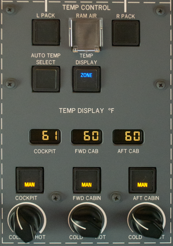
Photo: Temp Control Panel, Auto Temp Select Off, Temp Display Zone, Manual Mode, (Eddie's aircraft)
[G450 Aircraft Operating Manual, §2A-21-20, ¶2.C.]
With the AUTO TEMP SELECT push-button set to OFF (illumination extinguished), the TEMP DISPLAY push-button may be used to set the digital temperature readout to reflect the actual temperature in the air conditioned areas by depressing the button to the ZONE position (illuminated blue).
With TEMP DISPLAY in ZONE, you are reading the actual temperatures in each zone. You can do this with temperature control in AUTO or MANUAL. In the example photo we are in MANUAL mode and should monitor the DUCT temperatures instead, as shown below.
Manual Temp Control / Duct Temperature Displayed

Photo: Temp Control Panel, Auto Temp Select Off, Temp Display Duct, Manual Mode, (Eddie's aircraft)
[G450 Aircraft Operating Manual, §2A-21-20, ¶2.C.]
With the AUTO TEMP SELECT push-button set to OFF and the TEMP DISPLAY push-button set to DUCT (illuminated green), the digital temperature readouts reflect the actual temperature in the supply ducts to the air conditioned areas, read from temperature sensors downstream of the trim air valves. The TEMP DISPLAY push-button alternates between ZONE and DUCT each time the button is depressed.
With TEMP DISPLAY in DUCT, you are reading the actual temperatures in each duct. You can do this with temperature control in AUTO or MANUAL. In the example photo we are in MANUAL mode and this is what you should be monitoring.
If you are experiencing "pressure bumps" during descent it may be that your trim air valves are being too aggressive and rapidly changing the amount of air coming into the cabin. Some have reported they were able to smooth these bumps by going to manual temperature control. This keeps the air input relatively constant, everything else being equal.
Equipment Cooling

Figure: G450 Equipment Cooling Fans, (G450 AOM, §2A-21-00, figure 5)
[G450 AOM, §2A-21-20, ¶2.D.] The LEER and REER each contain an electrically-powered cooling fan. The Left PSU fan pulls air through ducts in the passenger compartment that are fitted with eyeball outlets for passenger ventilation. The Left PSU duct exhaust is directed into the top of the LEER to assist equipment cooling. LEER airflow is routed through the equipment racks and over the Left Power Distribution Box (PDB) by a fan before exhausting through louvers into the area beneath the forward cabin floor. The Transformer Rectifier Units (TRUs) are located in the compartment beneath the forward cabin floor and are cooled by the exhaust of LEER fan airflow. Airflow is assisted by an integral fan on each TRU. After passing through the underfloor compartment, the air is drawn upward into the bottom of the REER. The underfloor air circulates through the action of a fan in the Right PDB and mixes with the cooling air drawn into the top of the REER by the REER fan. The combined flow is then exhausted overboard through the Thrust Recovery Outflow Valve (TROV) that is located behind the REER.
[G450 Maintenance Manual, §21-25-00, ¶4.A.]
The LEER and REER fans have two speeds which are controlled by applying a ground to the logic pins. Each fan changes from a fast speed to a slower speed at 35,000 feet altitude. The air conditioning units energize two relays to ground the required pins to change the speed of the fans.
These relays are energized by the air conditioning control units. Only one air conditioning control unit has to be operating for the fans to change speed.
The baggage compartment EER cooling fan is powered by the left main 28 Vdc bus. The single speed fan comes on when the bus is powered and its circuit breaker is depressed.
The PSU fan is a two speed fan. It runs at a low speed until either of the environmental control system relays are energized at 35,000 feet and then shifts into high speed. The PSU fan is powered by the left main 28 Vdc bus and comes on when power is applied and when the circuit breaker labeled L PSU FAN, located in the LEER circuit breaker panel, is depressed. This fan also has a Low Speed Warning Detector (LSWD) attached. The LSWD inputs a discrete GND (ground) to the CAS when the fan speed drops below a predetermined speed. The CAS then displays the L-R EER Fan Fail (blue) or L PSU Fan Fail (blue) message.
This can be confusing, especially when you have to explain to a passenger why there is a hissing sound from the front of the cabin at high altitudes. The fans inside the LEER and REER are at high speeds at low altitude and the PSU fans are just the opposite. Why? At low altitude there is plenty of air flow and the LEER and REER get more than enough cooling air from the fans up front. At high altitude the TROV is more tightly shut, trying to keep the vessel pressurized. The PSU fans therefore kick into high speed to draw air from the passenger service units (the "gaspers"). The hissing noise you hear in the cabin is from the air being sucked in from the forward gasper duct. The sound can change depending on how many of the gaspers are open. (If all the gaspers are closed, the PSU doesn't have to work as hard and the volume of the hiss decreases.)
Zone Temperature Sensors
[G450 Aircraft Operating Manual, §2A-21-20, ¶2.C.]
Zone temperature readings are taken from temperature sensors that are positioned at variable locations within each zone. Location of the sensors is dependent upon airplane interior customizing and not fixed in production airplanes. Each temperature sensor has a dedicated fan to circulate zone air over the sensor. There are no controls associated with the fans.
The failure of temperature sensing information, auto temperature control circuits, trim air valves or a supply duct over-temperature will be sensed by the ACCs and a Crew Alerting System (CAS) message initiated prompting the flight crew to attempt manual control of zone temperatures.
Zone Temperature Sensor and Fan

Figure: Cabin zone temperature sensors, (G450 Maintenance Manual, §21-62-05, figure 401.
[G450 Maintenance Manual, §2A-62-00, ¶3.]
The cabin zone temperature sensor consists of the forward cabin zone temperature sensor and aft cabin zone temperature sensor. These sensors provide a means of sensing and control of the temperature in their appropriate zones.
The zone temperature sensor fans are provided for the forward cabin zone temperature sensor and aft cabin zone temperature sensor. These fans are required to draw ambient air across each zone temperature sensor to provide accurate reading and control of the temperature of the forward cabin and aft cabin zones.
The cockpit zone temperature sensor consists of the dual cockpit zone temperature sensor. These sensors provide a means of sensing and control of the temperature in their appropriate zones.
Why is this important? You need to know where the sensors are to make sure they aren't blocked or somehow affected by the environment. The cabin sensors have been greatly improved by using a fan to draw in air, as opposed to the older style that often became fooled when someone's coat found itself draped over the sensor. If your aircraft interior was well designed, you shouldn't have to worry about it. Here's where they are on my aircraft . . .
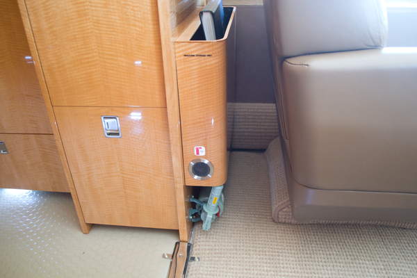
Photo: Aft cabin temperature sensor, (Eddie's aircraft)
This sensor incorporates a fan so you need only ensure nothing blocks it.

Photo: Forward cabin temperature sensor, (Eddie's aircraft)
This sensor also incorporates a fan so you need only ensure nothing blocks it.

Photo: Aft cockpit temperature sensor, (Eddie's aircraft)
This sensor does not incorporate a fan but seems to operate without outside interference.

Photo: Forward cockpit temperature sensor, (Eddie's aircraft)
This sensor is next to the pilot's leg and could be affected by the pilot's leg or clothing.
References:
Gulfstream G450 Aircraft Operating Manual, Revision 35, April 30, 2013.
Gulfstream G450 Airplane Flight Manual, Revision 36, December 5, 2013
Gulfstream G450 Illustrated Parts Catalog, Revision 17, October 31, 2012
Gulfstream G450 Maintenance Manual, Revision 18, Dec 12, 2013