Fuel System
- James Albright (a former G450 driver)
Updated: 2015-07-22
The G450 and G550 fuel systems are virtually identical, both borrowing heavily from the Classic GV which borrowed heavily from the GIV and all the way back to the GII. The G550 carries more fuel for longer, so it has a heated fuel return system that is not found on the G450. Some of the limitations are slightly different too. But if you learn the fuel system on one, you will be 99% there for the other.
The fuel system on both aircraft require very little crew interaction with just a few exceptions.
We will look at the complete system from the time the fuel enters the aircraft to the time it leaves the fuel tanks
Everything here is from the references shown below, with a few comments in an alternate color.
For fuel system abnormal procedures: G450 Fuel System Abnormals. If you would like 36 slides presented in refresher form: G450 Fuel System Refresher.
Overview
[G450 Aircraft Operating Manual, §2A-28-10 and G550 Aircraft Operating Manual, §2A-28-10]
The G450/G550 fuel system consists of two (2) wing fuel tanks, a series of pumps and lines to supply fuel to the engines and APU, and indicators to monitor the aircraft fuel state.
G450: The total usable capacity of fuel tanks is 29,500 pounds, or 4,370 U.S. gallons at a standard fuel weight of 6.75 pounds per gallon. The international equivalent is 13,380 kilograms or 16,542 liters.
G550: The total usable capacity of fuel tanks is 41,300 pounds, or 6,118 U.S. gallons at a standard fuel weight of 6.75 pounds per gallon. The international equivalent is 18,734 kilograms or 23,158 liters.
The fuel tanks can be filled from a single-point pressure fueling adapter or through tank fill openings on top of each wing. Fuel is drawn from the tanks and pressurized for distribution to the aircraft engines and/or APU by boost pumps mounted on the rear wall of each tank. Sensors mounted within the fuel tanks provide information for cockpit display windows enabling the flight crew to monitor fuel quantity and fuel tank temperature.
Single Point Pressure Fueling

Single point fueling, (Eddie's aircraft)
[G450 Maintenance Manual, §28-21-00, ¶4.A.(1)] During pressure fueling, fuel enters through the pressure fueling / defueling adapter. The fuel then flows through the main fill line to a cross fitting. From the cross fitting, fuel then flows though separate lines to a pressure fueling shut-off valve where it enters the main wing tanks. The pressure fueling shut-off valves are part of the fueling shut-off control system. Fuel flow through the shut-off valves will continue until the valves are closed by the fueling shut-off control system.
Pressure Fueling/Defueling Adapter
[G450 Aircraft Operating Manual, §2A-28-30 ¶2.A. and G550 Aircraft Operating Manual, §2A-28-30 ¶2.A.]
Both left and right fuel tanks may be filled from a single fueling point within a panel located in the right wing forward fuselage fairing. The fueling panel opens to provide access to a fueling receptacle and two valves used to check the automatic shutoff features of the pressure fueling system.
The GSCP is powered by the Ground Service bus and provides the indications and controls necessary to pressure fuel the airplane. After the desired fuel quantity has been selected with the GSCP, the shutoff control features of the pressure fueling system are operationally checked prior to fueling.
If atmospheric and tank pressures remain in balance, fuel in the control lines continues through an electrically operated solenoid valve. The solenoid valve may be closed by electrical signals from three sources:
The fuel quantity system when the preselected total fuel quantity has been reached.
The GSCP when the left TEST/RESET and AUTO REFUEL switch is placed in the center OFF position.
The REMOTE FUELING pushbuttons labelled L SHUTOFF and R SHUTOFF above the FUEL SYSTEM panel on the cockpit overhead.
If the solenoid valve is closed by electrical signals from any of these sources, pressure will build up in the fuel control line, exceeding atmospheric pressure, and causing the pressure sensing valve to close the fueling shutoff valve.
If you set a specific onload at the automatic refuel panel the fuel will eventually even itself out. If you ask for a specific amount without setting the panel in a G450, you will tend to load right wing heavy. This is the way it was in the GIV. For some reason the GV/G550 don't have this problem.
Do you need electrical power to refuel? No, the pressure-fueling and high-level shutoff valves do not require it. But you will need electrical power if you want to automatically shut off at a preset level.
More about how to fuel the airplane: G450 Fuel Servicing.
More about this: G450 Fuel Servicing.
Nobody does the precheck valve inspection for every refueling but you really need to do it if you are fueling close to capacity. You ought to consider doing this at least once a month even if you never get near full capacity, just to make sure the pressure check system works.
Auto Refueling Operation
Despite notes to the contrary, the panel doesn't default to manual refueling. If you mistakenly leave the switch in AUTO REFUEL, the system could shut off your fueling at whatever value was left in the PRESEL.
For more about this, see G450 Fuel Servicing.
Remote Fueling Shutoff

Figure: G550 fuel system control panel, (G550 Aircraft Operating Manual, §2A-28-00, figure 5)
You can electrically shut off fuel to either tank when refueling using single point pressure fueling using the remote fueling shutoff switches. These are powered by the ground service bus. If you place one of these switches to off and turn the ground service bus off, the valve will reopen.
Over Wing Refueling
[G450 Aircraft Operating Manual, §2A-28-20 ¶2.B. and G550 Aircraft Operating Manual, §2A-28-20 ¶2.B.] An over-wing (gravity) fueling adapter assembly is installed on the top of each wing near the wing tip. The adapter has a locking fuel cap and a sleeve intake into the wing tank. The sleeve is fitted with a screen filter to prevent foreign objects from entering the tank during fueling. Because of the length of the sleeve intake required to accommodate the fueling nozzle, the amount of fuel loaded using this method is slightly less than that if pressure fueling were used.
[G450 Aircraft Operating Manual, §09-02-10, ¶3.B. G550 Aircraft Operating Manual, §09-02-10, ¶3.B.] If fueling facility is not equipped for over-the-wing refueling both wings simultaneously, it may be necessary to alternate refueling each wing incrementally provided maximum fuel imbalance between both wings does not exceed 2000 pounds at any time during refueling operation.
More about this: G450 Fuel Servicing.
Wing Fuel Tanks
[G450 Maintenance Manual, §28-00-00, ¶3.A] Fuel is integrally stored in the left and right wings. Wing construction allows for most of the interior area of the wings to act as fuel storage tanks. Most areas between the front spar, rear spar, wing root and the wing tip is used for fuel storage. The wings, designed with a 3° positive dihedral, form a natural gravity feed system to the fuel hoppers located at the wing root. The fuel hoppers are isolated compartments within the tanks that are continuously supplied with fuel by gravity and a fuel ejector pump system. Fuel is removed from the fuel hoppers to supply the engines and APU. To prevent the outward flow of fuel during in-flight turns, ribs within the tanks are fitted with baffles and check valves hinged to open toward the wing root, thus ensuring the hoppers remain full at all times.
[G450 Aircraft Operating Manual, §2A-28-20 ¶1. and G550 Aircraft Operating Manual, §2A-28-20 ¶1.] The airplane wing fuel tanks are integral to the wing structure. Fuel is contained within most of the interior of the wing, with the tank dimensions defined by the front wing spar, rear wing spar and the upper and lower wing skin. The interior of the wing is coated with a sealant during manufacturing to prevent fuel leakage. The shape of the wing accommodates the installations necessary for efficient operation of the fuel system. The tank area near the wing root has the largest volume and houses the fuel boost pumps and fuel feed lines. With wing dihedral of 3°, fuel within the wing will always flow towards the wing root, ensuring that the fuel boost pump inlets will be adequately supplied until all usable fuel has been consumed. To prevent the outward movement of fuel during flight maneuvers involving turns, the five wing ribs within the tank that form the contour of the wing are fitted with baffles hinged to open only in the direction of the wing root. The wing ribs also contain a series of holes above the baffles to allow fuel to flow outboard during single-point pressure fueling, since the single-point access is located near the wing root. A second set of holes penetrate the wing ribs below the baffles to allow residual fuel and any accumulated water to drain inboard to the wing root as fuel quantity decreases.
Fuel Leaks
[G450 Maintenance Manual, §28-10-00, ¶1.B.]
(1) Determine class of external leak as follows:
(e) Classify leak from the following:
Seep - A fuel leak that wets an area around the source up to 1 1/2 inches (38.10 millimeters) in diameter but does not run or drip
Slow seep - A fuel leak that wets an area around the source up to 3/4 inch (19.05 millimeters) in diameter
Heavy seep - A fuel leak that wets an area around the source up to 3 inches (76.20 millimeters) in diameter but does not run or exceed two drops per minute
Drip - Any fuel leak that causes dripping from aircraft structure at a rate of three but not to exceed four drops per minute
Running leak - Any fuel leak that allows fuel to drip or run from aircraft structure at a rate of four drops per minute or greater
NOTE: The size of the wetted area described for seep, slow seep or heavy seep is limited by evaporation of fuel. When fuel evaporates from a wetted surface at the leakage rate, the wetted area will not enlarge.
CAUTION: ANY LEAK MAY BE AN INDICATION OF A STARTING STRUCTURE FAILURE.
(2) Repair external leak as follows:
NOTE: Source of leak must be located and cause determined prior to resealing.
(a) For seep / slow seep / heavy seep leak, record leak location, then clean surface and inspect frequently.
(b) For drip leak, investigate cause and repair as soon as possible upon returning to a suitable maintenance base.
(c) For running leak, ground aircraft and repair immediately.
For more about fuel leaks, see: G450 Fuel Leak Inflight.
Heat Exchangers
[G450 Aircraft Operating Manual, §2A-29-20 ¶2.B.] After pressurizing aircraft subsystems and components, [left] system fluid enters a radiator type heat exchanger located in the left wing fuel tank. The hot hydraulic fluid is cooled by fuel in the tank (and tank fuel is slightly warmed, although the high ratio of fuel to hydraulic fluid results in a minimal temperature rise) then returned to the system reservoir, after passing through a system return filter located in the filtration module.
[G450 Aircraft Operating Manual, §2A-29-30 ¶2.B.] Right system pressurized fluid follows a similar path as the left system, through the same sequence of acoustic filter, filter manifold, system accumulator, dedicated thrust reverser, to the tail-mounted flight controls and forward to the landing gear wheel well for powering the flight controls installed on the wing, through a pressure relief valve, into the radiator cooler in the right wing fuel tank hopper, through a return filter and back to the reservoir. The right system also includes plumbing to the motor section of the PTU and return.
[G550 Aircraft Operating Manual, §2A-29-30 ¶2.B.] After pressurizing aircraft subsystems and components, [left] system fluid enters a radiator type heat exchanger located in the right wing fuel tank. The hot hydraulic fluid is cooled by fuel in the tank (and tank fuel is slightly warmed, although the high ratio of fuel to hydraulic fluid results in a minimal temperature rise) then returned to the system reservoir, passing through the return filter en route.
[G550 Aircraft Operating Manual, §2A-29-30 ¶2.B.] Right Hydraulic System] Right system pressurized fluid follows a similar path as the left system, through the same sequence of acoustic filter, dedicated thrust reverser, system accumulator, filter manifold, to the tail-mounted flight controls and forward to the landing gear wheel well for powering the flight controls installed on the wing, through a pressure relief valve, into the radiator cooler in the left wing fuel tank hopper, through a return filter and back to the aft equipment bay to be available to power the PTU and return to the reservoir
The purpose of the hydraulic/fuel heat exchangers is to cool hydraulic fluid when there is low demand from the associated hydraulic components. A residual benefit is heated fuel. The G450 places on-side hydraulics to the on-side hopper, the G550 crisscrosses.
Heated Fuel Return Systems (G550 Only)
[G550 Aircraft Operating Manual, §2A-28-30 ¶2.F.]
The temperature of the fuel in the tanks is monitored to ensure that it remains within limitations. Two temperature bulbs, one in each tank, are mounted on the aft wing spar and penetrate into the fuel hoppers. The bulbs contain an element with an electrical resistance that varies with temperature. The resistance in the bulbs is monitored by the MAUs (left tank by MAU #1, right tank by MAU #2) and converted to a proportional voltage that is then translated into a digital format for display by the MWS.
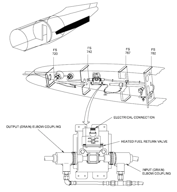
Figure: GV Backup heated fuel return valve, (GV Maintenance Manual, §28-16-00, figure 1)
When operating at high altitudes or in extreme latitudes, the temperature of the airplane fuel supply must be increased in order to ensure that fuel viscosity remains low enough for the fuel to flow freely through tank components and the engine Fuel Metering Unit (FMU). Fuel in the wing tanks is warmed by a Heated Fuel Return System (HFRS) that diverts a part of the fuel supplied to the engine back to the tanks. The fuel returned to the tanks is drawn off after it has passed through a heat exchanger with the engine oil system where hot oil is cooled by engine fuel. As a result, the temperature of the fuel is raised to approximately fifty degrees centigrade (50°C). The hot fuel is returned to the fuel tanks and distributed throughout the wing by a system of pipes with multiple small holes. Although the volume of hot fuel returned is much smaller than the cold fuel within the tank, the temperature difference is significant enough to warm the tank fuel to within the range to maintain required fuel viscosity.
There are a few things wrong with this paragraph:
At high altitudes the temperature is usually colder at lower latitudes, not higher latitudes. This seems contrary to common sense but it has to do with the height of the tropopause. More about this: High Latitude Operations / Temperature. The point here is you are more likely to see the need for HFRS over the equator than over the North Pole.
With a high volume of fuel, it has been my observation, that the HFRS does not raise the temperature of the fuel in the tank at all. It does, however, keep the fuel from getting colder than it is. After a few hours, all other things being equal, the temperature in the tanks of a G450 will be lower than a G550 because it does not have a HFRS.
Note that this is not "left over" fuel from the engine but fuel after warming by the oil/fuel heat exchanger on its way to the engine. Under situations of high fuel demand, greater than 2,250 PPH, the engine's demand will shut down the HFRS.

Figure: GV HFRS line installation, (GV Illustrated Parts Catalog, §28-16-00, figure 3)
Figure: GV HFRS line installation, (GV Illustrated Parts Catalog, §28-16-00, figure 3)
The flow of hot fuel back to the tank is controlled by three switches: one on the cockpit overhead and one at each engine. The FUEL RETURN OFF / AUTO pushbutton switch on the overhead FUEL SYSTEM panel provides flight crew control of the HFRS. When selected to the AUTO (or on) position, the return of fuel from the engine is managed by the Full Authority Digital Engine Control (FADEC) on each engine. The engine FADECs receive fuel tank temperature from the temperature probes fitted into each wing tank through the aft wing beam at the hopper. If the temperature within a wing tank is equal to or below zero degrees centigrade (0°C), the FADEC will open a Fuel Return To Tank (FRTT) valve at the engine, porting hot fuel back to the tank. When tank fuel temperature rises, equaling or exceeding ten degrees centigrade (10°C), the FADEC will close the valve, retaining the fuel within the engine FMU circulation. The operation of the FRTT valves are monitored by the MAUs, with MAU #1 communicating with the cockpit overhead switch and the FRTT valve of the left engine, and MAU #2 linked to the FRTT valve of the right engine. HFRS status is reported by the MAUs to the MWS that in turn formulates CAS messages appropriate to the operating condition and generates the graphic display of HFRS operation on the Fuel synoptic window. The Fuel synoptic window will display the HFRS only when the system is operating. The system is represented by a line and a valve between the respective tank and engine, shown in cyan. If the system is selected on and a malfunction exists, the line and valve are represented in amber.
The heated fuel is sprayed on top of the wing fuel throughout the tank. The illustration shows those piccolo tubes in the outboard section labeled "A" but there are also piccolo tube assemblies at positions "B" through "G" on both wings.
The operation of the HFRS is limited to fuel system normal operating parameters and also by airplane performance requirements, since the fuel returned to the tank must be in excess of the flow consumed by the engines as scheduled by the power levers and FADEC. For the FADEC to open the FRTT valve, the following conditions must be valid:
The cockpit overhead switch selected to AUTO
The engine fire handle stowed (not pulled)
Engine low fuel pressure not indicated
Engine low fuel quantity not indicated
Engine fuel flow requirement less than 2,250 pounds per hour
Fuel filter not blocked
Fuel crossflow valve closed
Fuel temperature should be at or below 0°C
Electrical power to the FRTT valve available
Fuel Quantity Indication
Capacitance Probes
[G450 Aircraft Operating Manual, §2A-28-40 ¶2.A. and G450 Aircraft Operating Manual, §2A-28-40 ¶2.A.] Each wing tank has [G450: 20, G550: 19] fuel quantity probes positioned throughout the tank. The probes are placed in positions that allow determination of fuel quantity for the full range of tank capacity, from full to lowest usable level. The probes are connected through a wiring harness that enters the tank through the forward wing spar The harness leads from the wing inboard, through the fuselage and up to the FQSC unit in the LEER. The probes measure quantity as a function of electrical capacitance. The FQSC transmits a low voltage signal (nominally 5 volts) to each probe through a wire in the harness and measures the capacitance through another wire in the probe. The ends of the two wires are separated by a fixed distance so that the capacitance between the wires is dependent upon the characteristics of the medium between the wires. The capacitance is higher when the probe is immersed in fuel and lower when the probe is exposed to air. The FQSC receives the capacitance signals from all probes in the wing and converts the combined signal to fuel quantity.
[G450 Maintenance Manual, §28-41-00 ¶3.B.] The fuel quantity probes are capacitors. The capacitance of the probes changes as the dielectric constant of the insulating medium between the capacitor electrodes changes. When the fuel tanks are full, the capacitance of the probes is greater than the probe capacitance when the fuel tanks are empty. Changes in fuel level cause a change in probe capacitance. This capacitive signal is supplied to the FQSC.
What is a capacitor? It is two conductors separated by an insulator. By placing different electrical charges across the conductors you establish an electrical field. The capacitance probe is a cylinder (one conductor) surrounded by a dielectric (the insulator) which is surrounded by another cylinder (the other conductor). The capacitance between the two tubes varies depending on how much of the tube is submerged in fuel. The FQSC measures all 20 (G450) or 19 (G550) probes and turns that into fuel quantity. Note there are no moving parts but aircraft attitude can influence readings since more or less of the probe will be covered by air.
Low Level Probes (G450 and G550) and High Level Probes (G550 only)
[G450 Aircraft Operating Manual, §2A-28-40 ¶2.A.] A separate probe is installed within the wing to provide a low fuel level signal to the FQSC. The low level probe is installed in the hopper, near the lowest level of the tank. When the fuel level drops to expose the probe to air, the capacitance falls and a low level signal is provided to the FQSC. The low level probe is positioned so that the low fuel level signal will occur at approximately 650 lbs.
[G550 Aircraft Operating Manual, §2A-28-40 ¶2.A.] Two separate probes are installed within the wing to provide high fuel level and low fuel level signals to the FQSC. The high level probe is positioned in the vent plenum so that when fuel quantity has reached tank capacity, the probe will be immersed and provide a high capacitance signal. The high fuel level signal is provided to the external refueling panel at the right wing root in order to illuminate the high level warning light on the panel door. The low level probe is installed in the hopper, near the lowest level of the tank. When the fuel level drops to expose the probe to air, the capacitance falls and a low level signal is provided to the FQSC. The low level probe is positioned so that the low fuel level signal will occur at approximately six hundred fifty pounds (650 lbs)
What about the fuel sloshing from tank to tank? When you roll crisply after takeoff you may notice a growing fuel imbalance of 500 lbs or more. You can transfer the fuel but will end up having to transfer it back. Or you can wait five or ten minutes and it takes care of itself. With the intertank and crossflow valves closed, there is no connection between tanks so do you have a problem? No. A crisp turn can put more fuel in the top part of a probe and momentarily fool the FQSC into thinking there is more fuel. Just give it a few minutes to figure it out. And stop rolling the airplane like a fighter.
Densitometer (G550 only) and Compensator
[G550 Aircraft Operating Manual, §2A-28-40 ¶2.A.] To refine the fuel quantity reading derived from the capacitance signals of the tank probes, two other types of sensors are installed in the tank. Each tank has a densitometer that determines the density of the fuel in the tank to improve the weight calculation of the FQSC. The densitometers are electromechanical oscillators that vibrate at a frequency proportional to the density of the medium surrounding the oscillator. The FQSC translates the frequency to density. The left tank densitometer is located in the tank hopper to monitor existing fuel density and the right tank densitometer is located outboard in the wing tank to measure fuel density as it is loaded in the tank.
[G450 Aircraft Operating Manual, §2A-28-40 ¶2.A. and G550 Aircraft Operating Manual, §2A-28-40 ¶2.A.] Each wing also has a compensator sensor placed in the fuel hopper to calculate the dielectric constant of the fuel. The dielectric constant is dependent upon the chemical makeup of the fuel, and different fuel brands or types have different additives that effect the dielectric constant. The right wing has an additional compensator outside of the hopper to determine the constant as fueling is in progress. The FQSC adjusts the capacitance reading of the fuel quantity probes using the dielectric constant reading from the compensator sensor.
Fuel Quantity Signal Conditioner (FQSC)

[G450 Aircraft Operating Manual, §2A-28-40 ¶2.B. and G450 Aircraft Operating Manual, §2A-28-40 ¶2.B.]
The FQSC processes signals from the wing tank fuel probes and compensators to provide accurate fuel quantity data for aircraft displays and control of the automatic refueling process. The FQSC is powered by twenty-eight volt (28 V) DC from the ground service bus. The ground service bus is in turn powered by the right main DC bus whenever an aircraft generator is operating. If the aircraft is on the ground (weight-on-wheels) and no generator is available, the ground service bus may be powered by an external DC cart or by the right aircraft battery. In order to preserve the integrity of the fuel quantity indication under all conditions, the FQSC may also be powered by the left and right emergency DC buses while in the air should the right main DC bus fail or be unavailable.
The Ground Service Control Panel (GSCP) receives fuel quantity from the FQSC through PDM/FSK data bus connections. During automatic refueling, the FQSC compares the preselected fuel quantity entered on the GSCP with the amount of fuel in the wings tanks and provides a signal to open the fueling solenoid valves until the preselected and actual fuel quantities match. The FQSC then closes the solenoid valves.
Quantity readings are furnished to MAU #1 and #2 by the FQSC over ARINC 429 bus connections. The MAUs forward data to the MWS for generating fuel quantity displays and Crew Alerting System (CAS) messages.
There isn't anything published about the accuracy of the fuel gauges. In the GIII we used to say any analog fuel gauge was only as accurate to 10% of the gauge's total indication, so plus or minus 1,500 lbs. Of course we made that up but it seemed safe. The G450 has many more probes and a dedicated computer to keep tabs on everything. The smaller Gulfstreams do publish this: G-100 Fuel Quantity Accuracy. So, for lack of any other metric, we can use 2% of the indication plus 0.75% of the full scale indication. Most of us use 3,000 lbs total as an absolute minimum. So on a tank we are only as good as plus or minus 0.02 (1,500) + 0.0075 (14,750) = 140 lbs.
Fuel Hoppers
[G450 Aircraft Operating Manual, §2A-28-20 ¶2.A. and G550 Aircraft Operating Manual, §2A-28-20 ¶2.A.] Each wing tank has a internal compartment at the wing root, termed a hopper, at the lowest point of the tank. Each compartment is formed by the rear wing spar, the rib at the centerline of the fuselage, an outboard wing rib and a wall located forward of the rear spar. The outboard wing rib and the forward wall have baffles directing fuel into the hopper, and drain holes for residual fluids.
The aft wing spar serves as the mounting surface for the boost pumps, fuel shut off valves, the crossflow and intertank valves and temperature sensors. The outside of the aft wing spar is accessible from the main landing gear wheel wells, and the fuel system components in the hoppers are mounted through openings in the spar, allowing the components to be replaced without emptying the fuel tanks.
Each hopper can contain 190 U.S. gallons or 1,283 pounds of fuel. The intake lines supplying the boost pumps are installed along the bottom of the hoppers ensuring that all possible fuel can be extracted from the tanks.
The ejector pumps are constantly overfilling the hoppers so they are always full, excess fuel goes back into the wing tank.
Fuel Tank Drains
Drain Valve Location

Figure: G450 Allen type drain valves, (G450 Maintenance Manual, §28-14-01, figure 401)
[G450 Maintenance Manual, §28-14-00, ¶1.A.] The fuel drainage system consists of 12 gravity water / fuel drain valves. They are flush mounted to the lower wing skin. Each is located at a fuel tank low point where water would collect after the aircraft remains stationary for a few hours. The drain valves provide points from where fuel samples can be taken, where water can be drained from the tanks without defueling and where residual fuel can be drained when completely defueling the tank. The aircraft is equipped with the following two types of drain valves:
Allen Aircraft Products INC (Allen type)
There are four of these on each lower wing panel: 1 inboard in the hopper under the ejector pump outlet, 1 inboard forward of the hopper wall, 1 outboard of outer hopper wall, and 1 outboard in the vent plenum.
Auto-Valve INC (Auto-valve type)
There are two of these on each lower wing panel just outboard from BL 0: 1 in fuel hopper aft of hopper wall and 1 in main tank forward of hopper wall
Drain Valve Operation

Figure: G450 Autovalve type drain valves, (G450 Maintenance Manual, §28-14-01, figure 402)
[G450 Maintenance Manual, §28-14-00, ¶4.A.] To drain water and residual fuel from tank, open poppet valve with a cross-slot (Phillips type) screwdriver. The poppet valve stem is pushed all the way in with the screwdriver to a hard stop. The poppet valve is rotated about 1/4 turn and then released. The poppet valve is locked in the open position. Holes in valve body allow water and fuel to flow out of tank. The poppet valve remains open until the stem is again rotated 1/4 turn and released. A spring closes the poppet valve and an O-ring engages the valve body to stop the flow.
If your operational rules permit you, the pilot, to do this, you really ought to practice it once or twice with a mechanic. The valves can be tricky to reseat and there are techniques to avoid getting yourself doused with fuel.
Fuel Tank Ventilation

Figure: G450 Fuel ventilation system, (G450 Maintenance Manual, §28-15-00, figure
[G450 Maintenance Manual, §28-15-00, ¶1.A.] The fuel ventilation system provides air and fuel vapor flow in or out of the fuel tanks. This prevents too much pressure or vacuum in the fuel tanks. The system relieves pressure when necessary by discharging fuel flow overboard via the fuel ventilation system vents. In flight, the ventilation systems lightly pressurizes each wing tank. The fuel ventilation system is fully automatic. In each tank, the system contains a forward and aft vent duct, a vent plenum, float-operated vent / relief valves, nonrelieving float vent valves, an overboard line and a flush vent inlet / outlet (vent / ram air inlet).
[G450 Maintenance Manual, §28-15-00, ¶4.A.] The two vent ducts extend parallel from the inboard vent valves into the vent plenum. Any fuel in the vent ducts and tubing drains back into the wing tank through drain valves installed in the ducts and tubing. The vent plenum allows air flow in and out of the tank and collects any overflow fuel from the vent ducts. If the overflow fuel fills the vent plenum, the excess fuel flows overboard through the overboard vent / ram air inlet. Air / fuel vapor flows in and out of the wing tank through the overboard vent / ram air inlet. During flight, air is pushed into the tank through the inlet.
Fuel Filtration
[G450 Aircraft Operating Manual, §2A-28-20, ¶2.E. and G550 Aircraft Operating Manual, §2A-28-20, ¶2.E.] The fuel system is protected from foreign particles by three filters in each tank. One filter prevents the entry of contaminants during over wing fueling. Two other filters are fitted into the fuel boost pump intakes at the bottom of the fuel hoppers. The mesh of the filters block the entry of particles into the fuel system but have no effect on liquid contaminants.
Fuel Tank Temperature Indication
[G450 Aircraft Operating Manual, §2A-28-30, ¶2.F.] The temperature of the fuel in the tanks is monitored to ensure that it remains within limitations. A temperature bulb mounted in the left fuel hopper contains an element with an electrical resistance that varies with temperature. The resistance in the bulb is monitored by MAU #1, and converted to a proportional voltage that is then translated into a digital format for display by the MWS.
[G550 Aircraft Operating Manual, §2A-28-30, ¶2.F.] The temperature of the fuel in the tanks is monitored to ensure that it remains within limitations. Two temperature bulbs, one in each tank, are mounted on the aft wing spar and penetrate into the fuel hoppers. The bulbs contain an element with an electrical resistance that varies with temperature. The resistance in the bulbs is monitored by the MAUs (left tank by MAU #1, right tank by MAU #2) and converted to a proportional voltage that is then translated into a digital format for display by the MWS.
Fuel Supply Valves
Engine Fuel Shutoff Valves
[G450 Aircraft Operating Manual, §2A-28-30, ¶2.D. and G450 Aircraft Operating Manual, §2A-28-30, ¶2.D.]
The engines are supplied pressurized fuel from the manifolds housing the dual boost pumps in each tank. The fuel is routed through a shutoff valve located on the aft wing beam at each tank. The shutoff valves are powered by the essential DC buses, left essential DC for the left engine and tank, right essential DC for the right engine and tank. The operation of the valves is controlled by the engine fire handles on the forward section of the cockpit center pedestal. Pulling out a fire handle will close the shutoff valve feeding fuel to the selected engine. For maintenance purposes, the valves may also be closed manually by using the position indicating lever on the valve body at the aft wing beam section in the main wheel wells.
The APU receives pressurized fuel from the left boost pumps and tank. A shutoff valve is installed in the APU fuel line at the left tank, and accessible through the left main wheel well. The valve is controlled by the APU MASTER switch on the cockpit overhead, and is also powered through the relay in the switch, using right battery bus or left essential bus DC.
The shutoff valves for the engines and APU are accessible from the wheel wells, and can be removed without defueling the airplane.
APU Fuel Shutoff Valve
The engine and APU fuel shutoff valves are motorized and are not spring loaded in either open or closed positions; they are "fail as they die" valves. If you need to undo the action of the fire handle for any reason, you can ensure the engine fuel shutoff valve remains closed by pulling the associated fuel shutoff circuit breaker.
Fuel Boost Pumps
[G450 Aircraft Operating Manual, §2A-28-30 ¶2.E. and G550 Aircraft Operating Manual, §2A-28-30 ¶2.E.] The airplane fuel tanks are equipped with four identical and interchangeable boost pumps, two in each tank. The boost pumps are located within the tank hoppers to ensure a positive supply of fuel to the pumps. The boost pump intakes are covered with filter screens to prevent the ingestion of foreign objects or particles that could damage the pumps. The boost pumps are designated main or alternate, with the main pumps installed in the inboard position, and alternate pumps outboard. Both main and alternate pumps are required to be selected on at all times, unless pumps in a tank are switched off to balance fuel between tanks. The main and alternate pumps are selected on with MAIN and ALT pushbutton switches on the FUEL SYSTEM panel on the overhead. The amber OFF legend in a switch will illuminate if the pump is selected off or if the pump is inoperative. The pumps are equipped with pressure sensors to monitor pump performance. When a pump is initially powered, the OFF legend will be illuminated until an operating pressure of 16 psi is reached. The OFF legend will illuminate with the switch selected on if pump pressure drops 16 psi and a CAS message will identify the failed pump.
The main and alternate boost pumps are electrically powered from different sources:
Left Main: Left Essential DC
Left Alternate: Left Main DC
Right Main: Right Essential DC
Right Alternate: Right Main DC
The pressure produced by the boost pumps is also used to provide fluid flow through the ejector pump in each tank. The ejector pump incorporates a small diameter line from the pressurized boost pump manifold plumbed to extend forward in the tank to a position in front of the intake baffle to the tank hopper. The ejector directs a stream of high pressure fuel into the mouth of a wider opening plumbed back into the hopper. The velocity of the fuel ejected from the pump induces the flow of a larger volume of fuel into the hopper, thus assisting in the movement of fuel into the boost pump intakes. Should both boost pumps fail, a separate line in the boost pump manifold, termed the suction bypass line, enables the engine to siphon fuel from the bottom of the hopper using the engine mounted fuel pumps. If the crossflow valve is open, boost pump pressure from the opposite side tank will be higher than engine suction pressure and the engine will be fed from the opposite tank.
Crossflow Fuel Transfer
Before we get started, let's take a look at a crossflow or intertank valve. They are the same, the part number is the same and they are interchangeable. Here is the valve closed:

Photo: Intertank (or crossflow) valve, closed.
Here it is open:
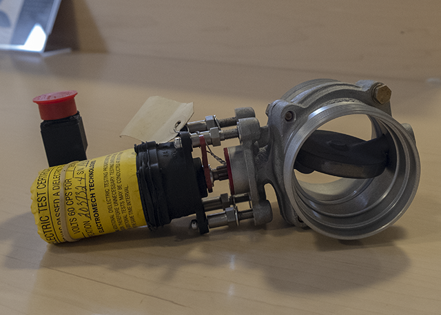
Photo: Intertank (or crossflow) valve, open.

Figure: G450 crossflow and intertank valves, (G450 Maintenance Manual, §28-24-00, figure 1)
[G450 Aircraft Operating Manual, §2A-28-30 ¶2.C. and G550 Aircraft Operating Manual, §2A-28-30 ¶2.C.] The crossflow line and valve is plumbed between the manifolds housing the two boost pumps within the hoppers of each tank, and allows an engine to be supplied with pressurized fuel from the opposite side tank. In the event of an engine failure, the remaining engine can be fed alternately from the onside fuel tank, then from the tank on the side of the inoperative engine to maintain fuel balance. Feeding an engine from the opposite side tank is accomplished by first opening the crossflow valve, turning on the boost pumps in the opposite side tanks, and then turning off the boost pumps in the onside tank. The crossflow valve is powered by the left essential DC bus.
While the book says all four boost pumps are identical and interchangeable, they don't all put out the same pressure and volume. You can find yourself with two boost pumps unable to overpower one boost pump through the crossflow valve. There are two philosophies on how to deal with this. Old school: simply switch pumps on the single pump side. New school: the Fuel Unbalanced checklist tells you to "Boost Pumps on Light Tank Side (one at a time) . . . OFF." It doesn't give you the option to balance fuel with only one pump off. I'm not sure I agree with the procedure. Remember that the engines may not adequately suction feed from the wing tanks above 20,000 feet so you should always have boosted pressure to the engine above that altitude. We've been crossfeeding with the one pump off method for decades. But it is up to you.
Intertank Fuel Transfer
[G450 Aircraft Operating Manual, §2A-28-30 ¶2.C. and G550 Aircraft Operating Manual, §2A-28-30 ¶2.C.] To enable balancing fuel between tanks in the event of dual boost pump failure within a tank, an intertank line and valve are installed between the two fuel tank hoppers. The valve is opened with the INTER TANK pushbutton switch on the FUEL SYSTEM panel on the overhead. Depressing the switch will open the valve and the white line legend will illuminate within the switch completing the diagram line between tanks shown on the panel. The intertank valve is also powered by the left essential DC bus. The fuel balancing procedure requires that the airplane be flown slightly out of trim in the yaw axis to induce fuel migration through the intertank valve. The out of trim condition will produce sufficient lateral force to cause fuel from the tank with the greater quantity to flow into the tank with the lesser quantity.
Though the crossflow and intertank transfer systems have been with us since the GII, for the most part unchanged, nobody really had it figured out until 2006. The crossflow works, but we've gone from a +10°C to a 0°C prohibition against turning boost pumps off inflight, to no restriction at all, and back to the 0°C restriction. That left us with the intertank valve which sometimes worked very well but at other times not at all.
If you look at the diagram above all will be revealed. While the pipes connecting both hoppers to the crossflow valve are pretty straight, not so with the intertank. The pipe in the left hopper is forward of the pipe in the right hopper, so all other things being equal the flow favors left to right. But all other things are not equal. Since the hopper is constantly being overfilled, if you open the intertank valve before establishing a sideslip the side with more pressure is likely to start fuel flowing to the side with lower pressure. By the time you get the sideslip in, it may be impossible to overcome the existing flow.
We didn't know any of this until Gulfstream studied it and published an article, Fuel Transfer Using Intertank System, in the 23 June 2006 Breakfast Minutes. The key change was to initiate 2-3 units of rudder trim in the direction of desired fuel transfer before opening the intertank valve. There are training materials out there from FlightSafety and others that still (as of August 2014) say "Balancing via the Inter Tank Valve requires the aircraft to gently side-slipped and fuel will flow from one hopper to the other." This is not true and if the prevailing hopper pressure is opposite your desired intent, it could make matters worse.
More about this: G450 Fuel Unbalanced.
Defueling
[G450 Aircraft Operating Manual, §2A-28-30 ¶2.B. and G450 Aircraft Operating Manual, §2A-28-30 ¶2.B.] Removal of fuel from the airplane may be accomplished by:
Attaching the pressure fueling nozzle into the adapter at the fueling panel and applying suction instead of pressure at the fueling truck. Two defueling lines (one for each tank) are connected to the pressure fueling inlet lines, but separated from the lines by one way check valves that remain closed under fueling pressure. When suction is applied to the fueling inlet lines, the check valves open, and fuel is siphoned from the airplane. The inlets of the defueling lines are located on the bottom of the fuel hoppers at the lowest point of the fuel tanks in order to remove the maximum amount of fuel possible from the tanks. However, approximately 11 gallons of fuel will remain within the tanks using this method. The water / fuel drains must be opened to remove residual fuel if the tank is to be totally emptied.
Connecting a 1 inch hose from the drain fitting on the fuel supply line to each engine and using fuel truck suction to draw fuel through the boost pump intake lines. This method results is less residual fuel in the tanks, but is much slower.
Using the same 1 inch line connected to the engine fuel line drain fitting and fuel truck, but powering the boost pumps to pressurize the engine supply line. This method is faster than method number two (2), and leaves the least amount of fuel in the tanks, since the boost pumps operate the ejector pump to induce greater fuel scavenging.
Defueling is easy, depending on where you are. If you are at a Gulfstream service facility, they will be happy to defuel you while they work on the airplane and then give you your fuel back. But it isn't so easy anyplace else. Few venders can store your fuel and redispense it to you, or are set up to dispose of it.
References:
Gulfstream G450 Airplane Flight Manual, Revision 35, April 18, 2013
Gulfstream G450 Maintenance Manual, Revision 18, Dec 12, 2013
Gulfstream G450 Operating Manual Supplement, G-450-OMS-02, Extended Operations (ETOPS) Guide, Revision 2, April 2, 2009
Gulfstream G450 Performance Handbook, GAC-AC-G450-OPS-0003, Revision 20, November 30, 2011
Gulfstream G450 Quick Reference Handbook, GAC-AC-G450-OPS-0003, Revision 34, 18 April 2013
Gulfstream G450 Weight and Balance Manual, Revision 3, March 2008
Gulfstream GV Illustrated Parts Catalog, Revision 24, August 31, 2005
Gulfstream GV Maintenance Manual, Revision 25, August 31, 2005