Powerplant
- James Albright (a former G450 driver)
Updated: 2019-02-02
The inner core of the G450 engine is basically the GIV Tay engine but there is little similarity beyond that. The engine accessories, control, and just about everything else more closely resembles the engine from the GV. That is a good thing.
Everything here is from the references shown below, with a few comments in an alternate color.
G450 Powerplant
[G450 AOM, ¶2A-71-10] The Gulfstream G450 is powered by two Rolls-Royce Tay-611–8C engines. The engine is a medium bypass ratio turbo fan with two concentric spools each containing compressor and turbine stages. The inner spool contains the large diameter fan stage and three low pressure compressor stages at the forward end that is driven by three turbine stages at the aft end of the engine. Since these three turbine stages are located within the larger diameter and cooler section of the engine exhaust where gases expand, the inner spool is referred to as the low pressure or LP turbine. The outer spool rotates freely around the inner spool and is termed the high pressure or HP turbine since it contains a twelve (12) stage compressor section at the forward end that is driven by two turbine stages positioned in the narrower high pressure section of the engine immediately aft of the combustion chambers. Each spool is supported by roller / thrust bearings that both enable rotation and maintain the position of each spool. The bearings are lubricated by a recirculating oil system that is cooled by a fuel-oil heat exchanger.
As the engine rotates (counter-clockwise when viewed from the front), the fan draws in a large volume of air and compresses it, forcing the air aft through the engine. Most of the air is ducted into the nacelle around the engine core, providing thrust and cooling the turbine section before mixing with and cooling the combustion section exhaust. The air flowing around the engine core is termed bypass air and the engine has a bypass ration of three point one to one (3.1 : 1), so only approximately one fourth (1/4) of all of the air drawn into the engine is ducted into the engine core for combustion. The fan air used for combustion is fed into the twelve (12) compressor stages of the outer spool. Each compressor stage increases the pressure of the air by interaction with stators between each compressor stage. As the name implies, the stators are fixed and do not rotate, however the angle of incidence of the inlet guide vanes directing LP air into the compressor is variable in order to control the level of pressure generated by the compressor stages.
The AOM "counter-clockwise" statement is a cut and paste error from the G550 manual. This engine spins clockwise when viewed from the front.
After the compressor stages, high pressure air is forced into a annular shaped combustion chamber. The circular chamber has ten (10) combustion liner assemblies that surround the core of the engine. The liners are numbered (for maintenance purposes) with number one (1) at the top center of the engine and the remainder numbered clockwise as viewed from the rear. Fuel is injected into the combustion chamber by ten (10) spray nozzles arranged in the combustion liners around the circumference of the chamber. Two ignitor plugs, positioned in combustion liners four (4) and eight (8) provide a high energy spark to ignite the fuel / air mixture.
The high temperature / high velocity air produced within the combustion chamber is first directed against the two high pressure (HP) turbine blades and subsequently the three low pressure (LP) turbine blades. The high energy of the rapidly expanding air produces rapid rotation of both the HP and LP turbine stages. Rotation of the turbine stages powers the rotation of the associated LP fan compressor stage and the twelve (12) HP compressor stages through the common shafts connecting the turbine and compressor stages. Two accessory drives are mounted on the engine: a high speed gearbox on the HP compressor and a low speed gearbox on the LP compressor. The accessory drives use a series of gears to step down engine rotation speed in order to drive components such as the hydraulic pump and electrical generator.
After dissipating substantial energy in producing the rotation of the turbine stages, combustion air enters the engine exhaust area where it is mixed with cool fan stage air flowing around the engine core within the nacelle. The engine exhaust section is fitted with a crenelated flange surrounding the inside of the nacelle to thoroughly mix the flow of fan and exhaust air. The resultant exhaust mix is lower in temperature and distinctly quieter enabling compliance with noise reduction regulations.
All engine operation is controlled by a Full Authority Digital Engine Control (FADEC) mounted at the twelve (12) o’clock position on each engine core. The FADEC is powered by a self-contained generator, but can use aircraft direct current (DC) if the generator fails. The FADEC is electrically linked to the cockpit power levers and switches and communicates with all three (3) Modular Avionics Units (MAUs) over ARINC-429 data buses.
A Quick Jet Engine Primer
It has probably been a very long time since you've been to class learning the basics of how a jet engine works. (Me too.) And chances are that academic jet engine was nothing like what is strapped to your G450. So here is my understanding of the jet engine basics as applied to our aircraft. If I got anything wrong, just hit the "contact" button on the bottom of the page and let me know.
We can examine this from the front of the engine to the back.
Fan

In the very front of the engine is a very large fan which is driven by the LP shaft which runs down the center of the engine and is turned by the HP turbine. The fan has two main purposes: to draw in large amounts of air (the "suck") for the compressor and to propel (the "blow") a lot of the air aft. This outer blanket of air not only acts as a propeller to provide thrust, but it also cools much of the engine and surrounds air expelled from the jet part of the engine, serving to dampen the sound.
Some manuals call the fan the "LP Compressor" but Gulfstream tends to call it, simply, the fan. It takes incoming air pressure and raises it slightly.
Compressor
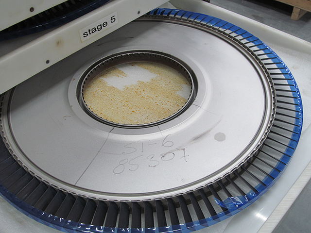
Photo: G450 Engine compressor, stage 6 (high pressure), from Eddie's aircraft
There are three low pressure compressor stages driven by the LP shaft and twelve high pressure compressor stages driven by the HP shaft. Each stage shapes the airflow as well as compresses the air for the next stage. The high pressure stages are more than just the rotating blades, there are stators the help to shape the airflow:
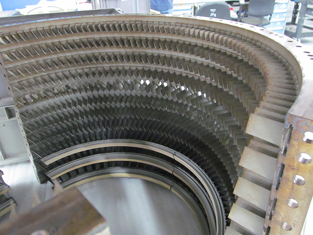
Photo: G450 HP compressor half case, from Eddie's aircraft
Some manuals call the three stages of compressors connected to the LP shaft in "IP Compressor," the "I" standing for intermediate. Everyone seems to have settled on "HP Compressor" for the twelve stages that follow. Whatever you call them, the combined effect of the Fan and the LP compressors about double the air pressure. The HP compressors raise the pressure by a factor of five.
Combustion Liners
Once the air is fully compressed it is divided between ten combustion liners where it is mixed with fuel. Two of the liners have igniters to get the flame going, but once the flame is going, the igniters can be turned off. The air pressure does not increase, but its velocity aft does.

Photo: G450 Combustion liners, from Eddie's aircraft
A quick word about thrust. Some pilots believe the "action-reaction" of a jet engine attributed to Newton's Third Law of Motion happens at the combustion liners, what many call the "burner cans." The exploding gas pushes forward on the cans so the cans push the engine which pushes the airplane. But that isn't true. The "action" is the mass of air accelerating aft, the reaction is the engine accelerating forward. So if you want to think of something pushing against the engine, it would be more correct to say every part of the engine in contact with the accelerating air is getting the "push."
Turbines

Photo: G450 HP turbine module stage 1, from Eddie's aircraft
The high velocity air expended from the combustion liners runs past two HP turbines and then three LP turbines. The air pushes against the rotating turbine blades to drive the shafts which drive the compressors.
Nozzle

Photo: G450 engine nozzle, from Eddie's aircraft
There is still a significant amount of potential energy in the air exiting the turbines. The purpose of the nozzle is to funnel the air to a smaller area so as to increase its velocity, converting it to kinetic energy.
Fire detection/protection
Each engine has a dual loop fire detector to sense heat levels associated with fire, the bleed air ducting is monitored for leaks by thermal switches, and the APU enclosure is monitored by a single element sensor. The crew is alerted to any excess temperature in these areas or to faults in the detection systems.
Engine Fire Detection and Warning
[G450 AOM, ¶2A-26-20 ¶2.A.] Each engine has dual loop sensors that provide indications of high temperatures associated with an engine fire. Sensors are located in the following positions:
At the engine compressor 7th and 12th stages
At the IDG
At the bleed air duct
Inboard of the engine on the fixed cowling near the front engine mount
The left engine (only) has a sensor positioned at the engine anti-ice duct
The sensors are located on the engine in rails. The sensors are wired together and act as a single dual loop sensor. The sensor loops are designated Loop A and Loop B. Additional redundancy is provided by separating the loop power sources: the left engine Loop A is powered by the left essential DC bus and Loop B powered by the right essential DC bus; right engine Loop A is powered by the right essential DC bus and Loop B by the left essential DC bus.
Each loop is a sheath of stainless steel surrounding a temperature sensitive glass / oxide material. Centered in the glass / oxide material is a coaxial cable wire. The electrical resistance and capacitance between the steel sheath and the center wire are monitored by a Fire Detector Control Unit located in the tail compartment of the aircraft. As a sensor loop is heated, the glass / oxide material loses insulating qualities and allows a current flow between the center wire and the surrounding sheath, signaling a fire. Both loops are located in parallel and at close proximity, so the control unit must receive a simultaneous fire indication from Loop A and Loop B to send a fire annunciation to the cockpit. If only one loop indicates a fire, the indication could result from a breach of the insulating glass / oxide material or other malfunction, and is reported as a loop fault by the control unit.
If both loops indicate a fire, the control unit sends a signal to the Modular Avionics Units #1 and #2 which send red Engine Fire, L-R CAS messages for engine fire and fire loop alerts. Control unit hard wire connections illuminate the engine fire handle and release the solenoid holding the fire handle in the stowed position, illuminate the engine fuel control switch, the master warning light on the cockpit glare shield and both loop A and loop B elements of the fire test switch for that engine.
If only a single loop indicates a fire, the control unit will generate a loop fault signal for that loop, illuminating the appropriate fire detection loop fault indicator and prompting Engine Fire Loop Alert CAS messages for fire loop alert and Engine Fire Detection Loop Fault. The erroneous loop may be selected off and fire detection will be accomplished with the single remaining loop. If a fire is detected when in single loop configuration, all indications and warnings are the same as dual loop detection except there is no loop fault indication for the loop selected off.
Each engine has two fire detection loops, each loop powered by a different DC essential bus. Both loops are monitored for faults and you can take a loop off line if it has a fault. It takes two loops to detect a fire unless you took one off line, then it only takes one. The MAUs send indications to the CAS, hard wire connections to the fire handles and fuel control switches. If you have an Engine Fire, L-R CAS warning, you might have a fire and need to check the fire fault switches. If you have a light in the fire handles and fuel control switches you have a fire.
An Engine Fire Loop Alert CAS message means one loop says there is a fire while the other doesn't; one of the loops is broken and you need to test to find out which. An Engine Fire Detection Loop Fault means the system thinks there is a problem and you need to investigate.
If you get an Engine Fire Loop Alert CAS message, or after successfully putting out an engine fire, you must test the fire loops.
If pressing a fire test switch light results in the normal eight indications — Loop A, Loop B, Engine Fuel Switch, Fire Switch, "Engine Fire Loop Alert" and "Engine Fire" CAS messages, and two Master Warn lights — the fire loops are okay and do not need to be disabled.
If pressing a fire test switch light results in a missing indication, the fire loop is faulty and the indicated loop should be disabled by pressing the applicable fire fault switch. Once the bad loop is disabled the good loop is on its own and the next thing you could see is the fire warning.

Pylon Overheat Detection and Warning

Figure: G450 Pylon access panels, from G450 Maintenance Manual, §26-12-00, figure 501.
[G450 MM, §26-12-20 ¶3.A.] Pylon thermal switches are mounted on the rib structure of the left and right pylons at FS 556, FS 580 and FS 651. There are three switches per pylon. The switches are normally open. When the ambient temperature near any of the switches rises above 250°F ±5°F, the affected switch closes. The left and right pylon thermal switches are electrically connected to the Modular Avionics Units (MAU). The left switches are powered with 28 Vdc from the left essential dc bus routed from the WARN LTS PWR #2 circuit breaker and through the equipment area overheat test relay #1. The right switches are powered with 28 Vdc from the right essential dc bus routed from the WARN LTS PWR #1 circuit breaker and through the equipment area overheat test relay #2. When any of the switches close, the circuit is completed to the MAUs. The MAUs then generate the applicable Pylon Hot, L-R message on the CAS.
Each pylon has three thermal switches which alert you with Pylon Hot, L-R CAS messages when air in the pylon itself exceeds 250°F.
APU Fire Detection

Figure: G450 APU fire detection loop, from G450 MM, §26-13-01, figure 402.
[G450 AOM, ¶2A-26-20 ¶2.C.] The APU fire detector is a continuous element routed around critical areas within the APU container. The element consists of a seven foot long tube filled with helium gas and a stabilizing chemical, sealed at both ends. Two sensors are installed in the end of the tube: one sensing high pressure and the other sensing low pressure.
If the gas within the tube is heated, a pressure increase above a preset threshold indicates a temperature of approximately 1,000°F over a small section of the sensor tube or by a temperature level of 450°F over the length of the sensor. When sensor pressure exceeds the threshold, a fire signal is sent to MAUs #1 and #3 for initiation of APU Fire CAS visual and aural fire warnings. Hard wire signals are generated to illuminate the FIRE legend on the APU overhead panel, the red master warning light on the cockpit glare shield and if the aircraft is on the ground (weight-on-wheels), to the APU fire warning horn in the nose wheel well. The APU ECU automatically shuts off fuel to the APU if a fire is detected.
The second tube sensor monitors low gas pressure in the fire detector. If an APU malfunction or other failure causes a rupture in the tube structure allowing the escape of the gas within, the sensor will detect the resulting loss of pressure and signal a failure of the APU fire detector to MAUs #1 and #2 to initiate APU Fire Detector Fail CAS annunciations.
The APU fire detection system is a simple helium tube inside the APU enclosure. If the pressure in the tube increases you probably have a fire; if it decreases you probably lost the detection system. An APU Fire CAS message means the MAU thinks you have a fire, a light in the APU fire light means you do.
Pneumatics
High temperature and pressure air comes from two compressor stages (7th and 12th) of each engine are fed into the bleed air system through pylon precoolers. Fan air ahead of the compressors is also used by the precooler.
Description
[G450 AOM, §2A-71-30 ¶2.A.] High pressure engine compressor air at elevated temperatures is supplied to aircraft systems through a common duct connected to valves located at the 7th and 12th stage of the engine HP compressor. At normal power settings, the pressure and temperature of the air drawn from the 7th stage of the HP compressor air is sufficient to meet system requirements. If the engine is operating a low power settings as during a prolonged descent, air of increased temperature and pressure will be extracted from the 12th HP compressor stage to satisfy requirements. A check valve in the common duct prevents 12th stage air from entering into the 7th stage of the compressor and disrupting airflow through the engine.
The operation of the 7th stage and 12th stage bleed valves is regulated by the Bleed Air Controller (BAC) of each engine. The BAC also maintains the temperature of the engine bleed air supply at a constant level by operating the bleed air precooler. The precooler is an air to air heat exchanger that uses cool ambient air extracted from the engine air inlet at the LP fan stage. The fan stage air circulates within the interior of the precooler to reduce the temperature of the 7th stage and 12th stage bleed air that passes through the precooler. The BAC opens and closes the supply valve from the engine fan stage to maintain engine bleed air at 400°F for normal operations. If higher temperature air is required because only a single engine or wing anti-ice valve is supplying bleed air, the BAC increases the regulated temperature of the air supply to 500°F by passing less fan stage air through the precooler.
For more about pneumatics, refer to G450 Pneumatics.
An independent bleed valve supplies warm air to the engine intake cowling to prevent the formation of ice. The bleed valve is controlled by the L COWL and R COWL anti-ice switches on the cockpit overhead panel. The switches may be used to electrically select the bleed valve open to provide ice protection or to enable the aircraft ice detectors to control the operation of the valve. Additional ice protection for the engine is provided mechanically by the rubber tip on the spinner of the fan stage compressor. The spinner tip is made of a soft elastic rubber compound designed to distort at the high centrifugal forces generated by engine rotation in order to dispel any ice buildup.
For more about cowl anti-ice, refer to G450 Cowl Anti-Ice.
Additional air bleed valves modulate engine performance. The valves are referred to as engine handling valves. The operation of the valves is controlled by the FADEC. During engine starting the bleed valves are open to promote engine acceleration. The FADEC closes the valves sequentially as engine rpm increases to a normal setting of 100%. The FADEC will also selectively open the bleed valves if an engine surge is detected.
For more about the FADEC, refer to Powerplant Control.
Fuel
There are three fuel pumps on each side. The boost pumps in the tanks get the fuel to the engines, in fact are required to do that above 20,000 feet. There is a low pressure pump in each engine whose only purpose is to keep the high pressure pump primed. The high pressure pump, in turn, keeps the engine fed with fuel. The Fuel Cooled Oil Cooler doesn't really do anything for the fuel, it is designed to cool engine and IDG oil. If the ambient air temperature is greater than 110°F, we have to worry about the fuel from getting too hot.
[G450 AOM, §2A-73-10 ¶1.A.] Fuel stored in the aircraft tanks is pressurized by the tank boost pumps and supplied to the engines after passing through the tank shutoff valves. Upon reaching the engine, fuel is further pressurized by a low pressure pump element, warmed in a heat exchanger containing engine oil, filtered and pressure monitored and supplied to a high pressure pump element that raises fuel pressure to the level required for engine operation. From the high pressure pump element fuel is again filtered and routed to the Fuel Metering Unit (FMU) that regulates fuel volume in response to commands from the Full Authority Digital Electronic Control (FADEC) as dictated by the cockpit throttles or autothrottles. Modulated fuel volume passes through a fuel flow transmitter and then is plumbed to ten burner nozzles in the combustion chamber.
Low Pressure Pump

Figure: Low pressure fuel pump, from G450 MM, §73-10-00, figure 2.
[G450 MM, §73-10-00 ¶3.A.] The function of the LP fuel pump is to keep the fuel pressure at the HP fuel pump inlet at a sufficiently high value to prevent cavitation. In specified conditions, subsequent to the failure of an aircraft tank booster pump, the LP pump can continue to supply fuel by suction. The LP pump is on the front face of the gearbox module.
The LP fuel pump is of the centrifugal type. It is turned directly by the related splined driveshaft in the external gearbox module.
Fuel from the aircraft tank, at booster pump pressure, goes into the pump inlet and to the center of an impeller. The impeller compresses fuel vapor back into solution, if it occurs, and increases the fuel pressure by the effect of centrifugal force. The pressurized fuel is supplied through a volute to the LP pump outlet and then flows to the FCOC.
They say the engines will run just fine with the boost pumps off all the way to 20,000 feet. The low pressure pumps are the reason, they provide enough suction to draw fuel from the hoppers.
Fuel Cooled Oil Cooler (FCOC)

Figure: fuel cooled oil cooler, from G450 MM, §73-22-01, figure 402.
[G450 MM, §79-20-00 ¶3.A.] The Fuel Cooled Oil Cooler has two cylindrical housings attached together one behind the other. This assembly is installed on the accessory suspension bracket above the oil tank. The function of the forward housing is to cool engine oil. And the function of the smaller rear housing is to cool the oil from the Integrated Drive Generator (IDG). Each housing has a different matrix assembly which lets hot oil flow around tubes that contain fuel which is at a lower temperature. Although the fuel supply is the same, the function of each housing occurs independently of the other. The engine oil cooler matrix is made of a series of small diameter parallel tubes which are installed through a number of baffle plates. Every second baffle plate has a hole in the center and is sealed around its circumference against the housing. This causes the oil to flow across the fuel tubes and back again as it moves through the length of the housing. The end plates of this matrix are sealed around the circumference to prevent fuel contamination of the oil. The fuel that flows through the tubes is then available to flow through the tubes of the IDG oil cooler matrix.
The IDG oil cooler housing is closed at the rear end and has an attachment flange at the forward end. The fuel tubes of the matrix have a U shape and they start and go back to an end plate which also has an attachment flange. Baffle plates give the oil direction across the fuel tubes. With the matrix installed in the housing, holes in the two flanges align with five studs on the engine oil cooler housing. Seals at each side of the matrix end plate prevent fuel contamination of the oil. There are two triangular flanges on the IDG cooler housing for the attachment of inlet and outlet IDG oil tubes. The engine oil cooler housing has an end cap which is installed on six studs at the front of the housing. This holds the matrix in position and a locating pin makes sure the end cap is correctly aligned with the housing. There is an opening in the end cap for the supply of low pressure fuel to the cooler assembly. Fuel goes out of the housing through an opening near the joint with the IDG cooler housing. Adjacent to the fuel outlet there is a position for the installation of a temperature probe to measure fuel temperature.
[G450 AFM, ¶1-24-20] The Integrated Drive Generator (IDG) electrical load is limited to 45% (18 kVA) when ambient temperature is greater than 110°F / 43.5°C in order to maintain steady state fuel temperatures below 95°C.
The 110°F IDG limitation exists because of the FCOC, a unique system in the GV type. I've never seen more than 26% load on an IDG so I suppose when it gets really hot, you just need to make sure you have two engines running or an engine and the APU.
Fuel Temperature Transducers
[G450 AOM, §2A-73-10 ¶2.D.] Two fuel temperature transducers are mounted within the fuel supply line at the exit of the FCOC. The transducers report fuel temperature to the FADEC that share the data with the MAUs and MWS in order to display engine fuel temperature on the Fuel and Summary synoptic windows.
Low Pressure Fuel Filter

Figure: LP fuel filter, from G450 MM, §73-10-00, figure 3.
[G450 AOM, §2A-73-10 ¶2.E.] The low pressure fuel filter is attached to the FCOC outlet and removes any debris or ice in fuel that might damage the high pressure pump. A pressure differential switch will supply a signal to the FADEC when the entering and exiting fuel pressures differ by five (5) psi to warn of an impending filter blockage. The FADEC communicates the condition to the Modular Avionics Units (MAUs) that in turn prompt the Monitor and Warning System (MWS) to display a blue “L - R Fuel Filter” CAS message to inform the flight crew of the condition.
[G450 MM, §73-10-00 ¶3.B.] The primary flow goes through the outer surface of the filter, through the filter material and into the space at the center of the filter. The material catches particles of contamination that are larger than 10 microns. The fuel flows out of the center of the filter to the fuel outlet connection in the housing. The fuel pressure transducer monitors the fuel pressure upstream and downstream of the filter. The transducer gives an indication on the flight deck EICAS display if the filter is almost clogged. There is no bypass around the filter if it becomes fully clogged.
[G450 QRH, page MB-34] Fuel Filter, L-R Retard power lever to 75% HP. Check that fuel temperature has increased to above +5º, and hold this condition for ten (10) seconds before restoring engine power. If engine operation becomes erratic, retard power lever. If engine continues to operate erratically, shut down engine. NOTE: If fault shows on both engines, apply above procedure to only one engine at a time. Land as soon as possible.
If you get a Fuel Filter, L-R you are hoping you have fuel icing and the QRH procedure solves the problem. If you don't, then you have to worry about contamination in the fuel and if that is the case, won't both engines be affected? Time to land.
Low Fuel Pressure Switch
Figure: Fuel pressure transducer, from G450 MM, §73-33-00, figure 1.
[G450 AOM, §2A-73-10 ¶2.F.] A low fuel pressure switch is installed adjacent to the filter assembly to monitor the fuel pressure prior to fuel entering the high pressure fuel pump. If sensed fuel pressure drops below 15 psi, the FADEC communicates with the MWS through the MAUs to prompt the display of a blue “L - R Engine Fuel Pressure” advisory CAS message.
High Pressure Pump

Figure: High pressure fuel pump, from G450 MM, §73-11-01, figure 402.
[G450 AOM, §2A-73-10 ¶2.G.] After filtration, fuel is directed into the high pressure pump. Unlike the centrifugal low pressure pump, the high pressure pump is a variable displacement pump consisting of a rotor and seven inclined cylinders. The pump incorporates an adjustable swash plate that varies the stroke of the pump pistons in order to provide the correct fuel flow for the given engine operating condition. The high pressure pump then routes the pressurized fuel to the Fuel Metering Unit (FMU) for modulation by the FADEC.
Fuel Metering Unit

Figure: Fuel Metering Unit, from G450 MM, §73-21-03, figure 401.
[G450 AOM, §2A-73-10 ¶2.H.] The fuel metering unit modulates fuel flow to the engine in response to commands from the FADEC. Modulation is accomplished by a metering valve that is equipped with a Linear Variable Differential Transducer (LVDT) that provides an electrical feedback signal to the FADEC to confirm that the metering valve is providing the fuel flow as commanded. The LVDT signal is also used to vary the displacement of the HP fuel pump in concert with fuel delivery demands.
The pressurized fuel within the FMU is used as a hydraulic force to control the position of the variable inlet guide vanes and variable stator vanes of the high pressure compressor. Vane position is determined by the FADEC adjusting the angle of attack of the vanes to optimize airflow generated by the rotating compressor stages. The FADEC electrically signals the FMU to port pressurized fuel to the increase or decrease angle side of the hydraulic actuator controlling variable vane position.
The cockpit FUEL CONTROL switches provide a manual means to control the fuel supply to the engines. The shutoff valve is also controlled by the engine FMU. When the cockpit FUEL CONTROL switches are on, the shutoff valve provides a means to shutdown the engine in the event of an overspeed of the low pressure turbine. The speed of each end of the low pressure turbine is monitored by an independent overspeed protection circuit. If the circuit detects an overspeed of one of the ends as would be the case in a broken turbine shaft, the FMU will signal the high pressure shutoff valve to close, interrupting fuel flow and shutting down the engine.
Fuel Flow Transmitter
Figure: Fuel flow transmitter, from G450 MM, §73-30-00, figure 1.
[G450 AOM, §2A-73-10 ¶2.I.] After the FMU has regulated the fuel supplied to the engine, fuel flow is measured by a transmitter downstream of the FMU. The gravimetric type engine fuel flow transmitter reports fuel usage to the FADEC that in turn transmits the data to the MAUs The MAUs subsequently supply fuel flow information to the MWS for display on the Fuel synoptic page and the Engine system page.
There is one fuel flow transmitter per engine, each located between the fuel metering unit and the fuel manifold.
Fuel Manifold and Fuel Spray Nozzles

Figure: Fuel manifold spray nozzles, from G450 MM, §73-10-00, figure 5, sheet 1.
[G450 MM, §73-10-00 ¶3.D.] The fuel spray nozzles mix the primary fuel flow with the pressurized air supply from the HP compressor. This makes a satisfactory fuel / air mixture that will burn satisfactorily in the combustion system.
There are 10 nozzles of the air spray type. They are installed at equal distances around the diffuser case. Each nozzle has a support and an air / fuel swirler assembly. The support contains an internal stem which has the function of a heat shield. At the inlet of the stem is a restrictor which controls the quantity of fuel that is supplied through the support and swirler assembly. The swirler assembly aligns with an opening in the related combustion liner. The swirler assembly contains a center air swirler, an outer air swirler and a fuel swirler. These swirlers contain angular vanes that change the axial straight flows into axial circular flows.
Pressurized fuel from the primary flow goes into the inlet at nozzle location 6. It then flows out through the nozzle outlet and flows through each rigid tube and adjacent nozzle. It also flows through the restrictors at the inlet to each stem. It then flows to each fuel swirler which changes the fuel from a straight flow to an axial circular flow.
Pressurized air (at P30 pressure) flows into the center air swirler of each nozzle. The center air swirler changes the axial straight air-flow into an axial circular flow. This circular flow is in the opposite direction to the flow from the fuel swirler outlet. This mixes the fuel with the air satisfactorily.
Ignition
There are two igniters per engine controlled by two EEC channels which you can activate automatically using the Engine START master, manually using the CONT IGNITION switches, or have the FADEC automatically select for a quick relight or an auto relight. Oh yes: igniter or ignitor? The manuals go both ways.

Figure: Ignition system schematic, from FlightSafety G450 Pilot Training Manual, figure 7-33.
[G450 Aircraft Operating Manual, ¶2A-74-10 ¶1.A.] Each engine has two ignitor plugs each powered by a dedicated exciter box. The ignitors are installed in the combustion chamber to ignite the fuel / air mixture injected into the chamber by the fuel nozzles and the high pressure compressor. Each ignitor plug provides a high voltage (1.8kV) pulse of energy supplied by a ignition exciter. The exciters transform 28v direct current from the aircraft electrical system to a 10 Joule energy pulse routed to the ignitors through shielded electrical leads. The exciters are mounted side by side beneath the combustion chamber of the engine. The igniter plugs protrude into the engine combustion lines with the number 1 ignitor located in combustion liner number 4 and the number 2 ignitor in combustion liner number 8. (The combustion liners are numbered 1 through 10 with number 1 at the top of the engine and the numbers increasing clockwise when the engine is viewed from the rear.) When the ignitors are selected on, the exciters send the high voltage pulse to the plugs at a 1 Hz cycle. When the engine reaches starter disengagement speed (41% N1), ignition is discontinued since the combustion of the fuel / air mixture is self-sustaining.
Ignition is controlled by the engine FADEC in response to switch commands on the ENGINE START panel on the cockpit overhead, commands from the FUEL CONTROL, L CONT IGN and R CONT IGN switches on the cockpit center console, or automatically if the FADEC detects an engine flameout with the engine running at idle or above.
Ignition Exciter Units
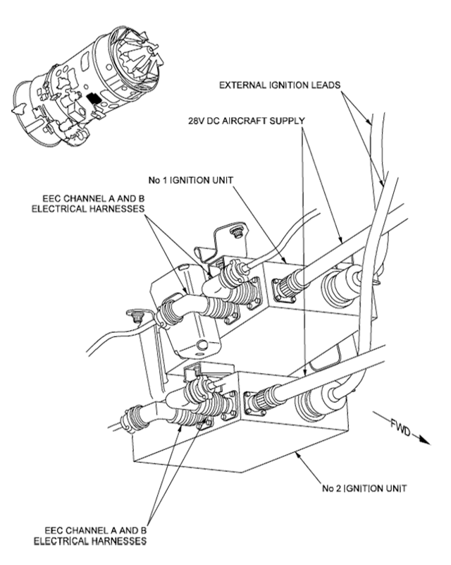
Figure: Ignition units, from G450 MM, §74-10-00, figure 1.
[G450 Aircraft Operating Manual, ¶2A-74-10 ¶2.A.] The ignition exciter units provide a capacitive discharge high energy pulse to the ignition leads and plugs. Ignition exciter 1 is powered by the left essential DC bus through the L/R IGN #1 circuit breaker. Exciter number 2 is powered from the right essential DC bus through the L/R IGN #2 circuit breaker. The exciters use inverters, transformers and capacitors to boost the 28v power supply to a ten Joule discharge with a minimum spark energy at the igniter tip of two Joules (2 J).
Each ignition exciter unit transmits the ignition energy pulse to the ignitor through a shielded lead that runs from the bottom of the engine to the ignitors in the two combustion liner chambers. The leads contain a multi-strand wire surrounded by flexible mesh insulation. The ignitor leads connect to the inner electrode of the ignitor plugs. The inner electrode is surrounded by a ceramic insulator and encased within a surrounding outer electrode. When the capacitance of the energy pulse from the exciter reaches the required level, the pulse discharges from the inner electrode to the outer electrode providing ignition to the combustion chamber.
The "ignition exciter units" in the AOM are simply "ignition units" in other publications. You can think of them as ignition coils in older cars.
Igniter Plugs

Figure: Igniter plugs, from G450 MM, §74-20-00, figure 3.
[G450 Maintenance Manual, ¶74-20-00 ¶3.B.] The igniter plugs which are the surface discharge type, are installed through the combustion case and into the combustion chamber. Each igniter plug has a center electrode and an outer electrode which are stored in a case. The center electrode has an iridium tip and is the positive electrode which connects to the inner wire conductor in the ignition leads. The outer electrode is the negative electrode and connects to the outer conductor in the ignition lead. The two electrodes are kept apart with a ceramic insulation material. At the tip of the igniter plug, between the electrodes, there is a semi-conductor pellet.

Figure: Burnt igniter plugs, looking into the plugs, from Eddie's broken airplane.
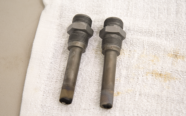
Figure: Burnt igniter plugs, top view, from Eddie's broken airplane.
So how long will an igniter plug last? Speaking from personal experience, the answer is eight. Our original plugs were installed when the engines were brand new in 2008. Eight years later we, okay me, decided it would be prudent to replace all four of them. Eight months later they have all failed. So eight years or eight months, depending on which batch of igniters you got.
Continuous Ignition (L/R CONT IGN) Switches
[G450 Aircraft Operating Manual, ¶2A-74-10 ¶2.C.] Although a single ignitor is normally powered only during the engine starting sequence to provide an ignition source until engine combustion is self-sustaining, the flight crew may select the continuous operation of both ignitors in each engine using the L CONT IGN and R CONT IGN switches on the center console aft of the power levers. The use of continuous ignition is advisable when encountering unstable air and/or precipitation, even though the FADEC will automatically select continuous ignition if an engine flameout is detected. The continuous ignition switches are also employed when using the alternate engine starting procedure and when performing abnormal engine operations.
Ignition Operation
[G450 Aircraft Operating Manual, ¶2A-74-10 ¶3.A.] During a normal engine start, only one ignitor is energized to initiate combustion within the engine. The ignitor is powered when the fuel control switch is selected to RUN and continues to provide ignition pulses until reaching stabilized engine rpm, usually at approximately 41% HP.
To prolong ignition exciter / ignitor service life, the FADEC alternates control channels and ignitor selection during each normal engine start. Switching occurs each time that the FUEL CONTROL switch is selected OFF.
During flight, the FADEC will automatically activate continuous ignition using both ignitors during an auto relight of the engine if the FADEC detects an abnormality in LP, HP or TGT parameters.
The EEC will also provide a quick relight function during flight if the FUEL CONTROL switch is selected OFF and then RUN. During a quick relight, the EEC will demand fuel ON and energize both igniters for a fixed time after the engine has reached idle.
[G450 Aircraft Operating Manual, ¶2A-76-20 ¶1.] Both channels of the EEC have independent connections to engine pressure and temperature sensors as well as independent electronic circuits for control of engine operation. Although both A and B channels are powered whenever the engine is operating, only one channel controls the engine. (The FADEC switches control authority between the channels at each engine shutdown.)
[Gulfstream G450/G550 Program Update, Volume 2, Edition 4, Quarter 1 2017, p. 15] According to the below logic there may be the case that you have two (2) unsuccessful starts in a row; if one ignition system is inoperative.
EEC channel A / igniter 1
EEC channel B / igniter 1
EEC channel A / igniter 2
EEC channel B / igniter 2
About ten years ago the only place I found this written was in the FlightSafety G450 Maintenance Training Manual and it has been taught in classroom after classroom. A few years ago it was repeated in a Gulfstream G450/G550 Program Update. I'm not so sure they have the order exactly right. I've memorized "A1, B1, A2, B2" but noticed a few examples where it just wasn't that way. I've seen "A2, B1, A1, B2" in one example, see the video: G450 Engine Start Igniter Check. But the point is clear: if you have a bad igniter you could end up with two bad consecutive starts using the START switch. If you want to start the engine for sure, selecting CONT IGNITION will ensure both igniters are energized.
If you are trying to trouble shoot an inconsistent start, it is even more complicated than just the four lines from the FSI manual. Each engine has its own EEC, each EEC has two channels, and each engine has two igniters. You don't normally know which channel and which igniter each engine is using. If you want to know, there is a way found in the G450 Maintenance Manual, §74-11-01, though it can be a bit of a chore finding the steps. Here they are:
Select the CMC
Select SYSTEM DIAGNOSTICS
Select 73_ENGINE_FUEL_AND_CONTROL / 21_ENGINE FADEC_LA / DATA: CONFIGURATION FADEC LA
That gives you this:

Photo: CMC Ignition Selection, from Eddie's airplane.
But keep in mind the ignitor line doesn't illuminate until you actually attempt a start.
Control/Thrust Management
The things in the cockpit we normally call "throttles" are actually power levers, as these engines don't have throttles. The engines are controlled by Full Authority Digital Engine Controls (FADECs) which are electronically connected to power levers in the cockpit. The FADECs measure engine performance using Engine Pressure Ratio (EPR), which on this engine isn't really EPR at all. None of that matters, because the power levers are normally controlled by the autothrottles which are controlled mainly by the FMS. Confused? Read on.
[G450 Aircraft Operating Manual, §2A-76-10] The Full Authority Digital Engine Control (FADEC) provides independent engine performance control and monitoring in response to flight crew switch position and power lever position commands. Each FADEC communicates with the Modular Avionics Units (MAUs) over ARINC-429 data buses to receive Air Data Module (ADM) information from aircraft environmental systems such as the pitot static and Total Air Temperature (TAT) probes. Each FADEC also transmits data to the MAUs and Monitor and Warning System (MWS) for use in providing synoptic and system window displays of engine performance as well as engine related Crew Alerting System (CAS) messages.
Although the flight crew monitors engine performance on cockpit displays, FADEC control of the engine is not transparent to the crew. The FADEC uses dedicated sensor and control circuits to gage engine operation and independently modulate engine components such as the Fuel Metering Unit (FMU), engine handling bleed valves, the position of the variable inlet guide vanes and thrust reversers to maintain engine performance at the desired level.
Power Levers
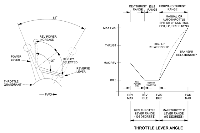
Figure: G450 thrust management system overview, from G450 AOM, §2A-76-00, figure 2.
[G450 Aircraft Operating Manual, §2A-76-30 ¶1.] Flight crew management of engine thrust is accomplished by manual or autothrottle movement of the power levers on the center console. Thrust settings are monitored by reference to the indications on the selected display window (Engine, Alternate Engine or Compacted Engine 1/6 windows). The power levers signal thrust commands through Rotary Variable Displacement Transducers (RVDTs) incorporated into the power lever mounts beneath the cockpit console panel. Each engine power lever RVDT has two channels linked to the corresponding channels of the Electronic Engine Controller (EEC) within the Full Authority Digital Engine Control (FADEC). Power lever movement thus results in the controlling EEC channel adjusting fuel flow to the engine to match the thrust setting dictated by the power lever.
[G450 Aircraft Operating Manual, §2A-78-20 ¶4.B.] When the EEC detects an uncommanded reverser deployment in flight, it reduces engine LP rpm to idle to minimize the effect on aircraft control stability.
While there is no mechanical linkage between the power levers and the engines, the power levers do move on their own in response to autothrottle and engine synchronization control. The only time they do not respond to engine power setting is in response to an uncommanded thrust reverser deployment in flight. There is no "throttle snatcher."
Autothrottle System
[G450 Aircraft Operating Manual, §2A-76-30 ¶2.C.] The autothrottle system is a function of software integrated into the Flight Management System (FMS). The autothrottles are engaged and disengaged by manual selection of switches located on the power levers. The autothrottles will also disengage if the flight crew manually changes the power lever position set by the autothrottles. The power levers additionally incorporate a pushbutton on the outside of each power lever knob that immediately selects the takeoff or go around power lever position.
When the autothrottle system is engaged for takeoff, the FMS will drive the power levers forward to the thrust setting selected on the MCDU takeoff initialization page. During takeoff, the FMS will maintain a constant power lever position after the aircraft has accelerated through 60 knots. The fixed power lever position is maintained until 400 feet, at which time the FMS will position the power levers to the climb power setting selected on the PERFORMANCE INIT page of the MCDU.
The autothrottles latch during takeoff at 60 knots and simply clamp the levers to that position until 400 feet. If you do not have the power levers in the correct position by 60 knots, you will not have the correct power setting when they latch. You will get the "HOLD" annunciation on the PFD no matter where the power levers are set. That's why your 60 knot callout, "power set, elevator free," requires you to look at the EPR gauges to ensure you have the correct power set.
With both autopilot and autothrottle engaged, the flight crew can control aircraft speed by entries made on the MCDU or by manual selections made on the Flight Guidance Panel. Guidance panel entries are made by depressing the pushbutton below the speed window and manually rotating the CHG knob between the pushbutton and the speed window. The autothrottle will change power lever position to achieve the selected speed. Any manual selection made on the guidance panel will override selections programmed with the MCDU.
A sub-function of the autothrottle enables the flight crew to synchronize the engines in order to reduce noise in the aircraft cabin. The crew can select synchronization of either EPR, LP rpm or HP rpm using the Display Controller TRS menu.
Electronic Engine Control
[G450 Aircraft Operating Manual, §2A-76-20 ¶1.] FADEC engine control functions are hosted within the Electronic Engine Control (EEC). The EEC is a dual channel fully redundant unit. The channels are denoted as A and B. Each channel of the EEC has two circuit boards that contain the software for engine control. One circuit board is the Central Processor Unit (CPU) and the other contains the interface to the dedicated power supply and the independent overspeed monitoring function. Both channels of the EEC have independent connections to engine pressure and temperature sensors as well as independent electronic circuits for control of engine operation. Although both A and B channels are powered whenever the engine is operating, only one channel controls the engine. (The FADEC switches control authority between the channels at each engine shutdown.) The redundant channel acts as a standby unit, available to assume engine control in the event of failure of the active channel. The active channel is continually monitored for performance by an internal circuit termed a “watchdog timer”. The timer actively interrogates the controlling channel and requires a response within a specified time frame. If the timer does not receive the expected response, engine control is temporarily shifted to the alternate channel while the previously controlling channel is reset.
There used to be a glitch in the engine that would fool the inactive channel into thinking the reverser was unlocked because it registered the reverser position just before the active channel registered the reverser stowed during the taxi check. When an MAU malfunction caused the EEC channels to switch in flight, the crew ended up with the engine pulled back to idle and ended up landing that way. Knowing the EECs switch channels every time the fuel control switch is placed to OFF, the crew could have got the engine back by simply shutting it down with the fuel control switch and restarting it.
Power Supply Unit (PSU)

[G450 Aircraft Operating Manual, §2A-76-20 ¶2.A.] The EEC channels are powered by a dedicated generator attached to the engine accessory gearbox. The generator consists of rotating permanent magnets within a field winding that produces three phase Alternating Current (AC). Some of the output of one phase is used to power the Independent Overspeed Protection (IOP) circuit prior to all three phases being rectified by the PSU into 28v DC that is the normal power source for the EEC. Since power from the dedicated EEC generator is not available until the engine is running, aircraft electrical system DC power is provided to the active EEC channel by the PSU during engine starts. The left essential DC bus powers EEC channel A and the right essential DC bus powers channel B of both engine FADEC EECs until the engine being started reaches approximately 35% High Pressure (HP) rpm. As the engine accelerates, sufficient power is produced by the EEC generator to support control of engine functions for the remainder of the starting process.
Each engine EEC relies on aircraft power, DC essential, until its dedicated generator takes over. The dedicated generator is connected to the same gear box as is the starter, which brings the engine up to about 42% HP rpm. At about 35% HP rpm the dedicated generator begins to power the EEC.
Data Entry Plug (DEP)
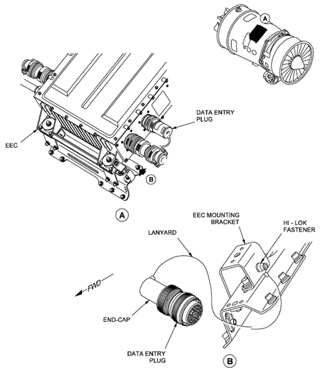
[G450 Aircraft Operating Manual, §2A-76-20 ¶2.D.] A data entry plug is installed on the engine to program engine performance values into the EEC. Programming is required only after an engine change or after major engine repairs. Data entered via the plug include TGT limits, Engine Pressure Ratio (EPR) to engine thrust produced as determined by calculated and engine testing values and thrust relationship to power lever RVDT values. Entering this data into each engine contributes to symmetrical engine response to autothrottle and power lever inputs. If faulty data is programmed into the EEC, the engine will revert to the alternate control mode where thrust is set using LP (N1) speed.
[G450 Maintenance Manual, §73-21-02 ¶1.] The Data Entry Plug (DEP) sets configuration of the engine in relation to the TGT, EPR trim index values and engine rating. Configuration set in the DEP is applicable to one engine only. It is directly related to the engine manufacturers type-test of that engine.
In the GV some would teach the DEP was connected to the engine because it would learn from the engine's history and therefore could teach a new EEC how to control the engine. That was and is not true. The DEP simply contains engine trim data from when the engine was first built and is unique to each engine.
Keep Out Zone (KOZ)
[G450 Aircraft Operating Manual, §2A-76-20 ¶3.A.] In order to prevent engine damage from fan stage flutter and vibration, the EEC will prevent the engine from operating within a rpm zone that is detrimental to the engine while the aircraft is on the ground (only). The rpm range is approximately 60-72% LP RPM, however the boundaries of the range are adjusted for temperature and may vary slightly. If the throttles are set such that the engine would normally be within the KOZ range, the EEC will increase or decrease rpm to avoid the hazardous region. The rpm will change according to the regime of engine operation - static run, taxi or reverse thrust. The following are the parameters for KOZ activation:
LP operating in the 60-72% LP RPM range (temperature adjusted)
Weight On Wheels (WOW) in GND mode
PARK/EMER BRAKE in the ON position (if airplane is static)
Ground speed less than 31 knots (if airplane is moving)
Once the EEC KOZ logic has been activated, the engine rpm will remain latched at the increased or decrease level until one of the listed parameters has changed or the throttles positioned outside of the KOZ.
Note the KOZ has changed from 62 - 70% LP RPM to 60 - 72% LP RPM. Note also that it only applies on the ground and the only time you are protected automatically is when the parking brake is set. You will see this in action if you ever do an engine run or try to do a cross-bleed start.
Engine Pressure Ratio (EPR) Control

[G450 Aircraft Operating Manual, §2A-76-30 ¶1.] The primary thrust setting reference on the Engine window(s) display is Engine Pressure Ratio (EPR). EPR is defined as the ratio of pressure sensed at the exit of the High Pressure (HP) compressor to the pressure of the ambient atmosphere as sampled within the engine bypass air duct. The ratio measures the increase in ambient pressure generated by the action of the engine compressor stages and the energy of combustion driving the engine turbine stages. EPR is measured by the engine EEC and communicated to the Modular Avionics Units (MAUs) for use by the display systems. The EPR value is not a true indication of actual engine thrust since it does not measure the propulsive force generated by the LP fan stage air that effectively contributes a thrust component equivalent to some turbo propellers. EPR is used for thrust management because it most accurately measures the internal forces of the engine compressor and turbine stages.
The definition of EPR varies by aircraft and it almost never means what you were taught in primary jet pilot school.
More about this: Engine Pressure Ratio.
[G450 Aircraft Operating Manual, §2A-76-30 ¶2.A.] Engine Pressure Ratio is computed by the EEC by comparing ambient air pressure to the pressure within the engine aft of the High Pressure (HP) compressor. Four interconnected ambient air pressure probes, each with five nozzles take readings of air pressure within the engine bypass duct. The probe readings are temperature compensated by the EEC to derive true ambient air pressure. The ambient air pressure is compared to the air pressure produced aft of the High Pressure (HP) compressor as sensed by an air pipe connected to two transducers - one for each EEC channel. The ratio of ambient air pressure to compressor outlet pressure is measured by the EEC as EPR.
Low Pressure Rotor Speed (N1) Control
[G450 Aircraft Operating Manual, §2A-76-30 ¶2.B.] If a malfunction or failure results in the loss of EPR data to the EEC, an alternate means of controlling thrust by regulating Low Pressure (LP) rotor speed (N1) is available. LP speed is monitored by three magnetic probes surrounding a phonic wheel mounted on the LP rotor shaft. The sensors magnetically measure rotor speed and electrically signal the rpm value to the EEC. Software within the EEC will revert to a programmed relationship between power lever RVDT position and LP speed control. If a failure causes an EEC reversion to LP engine control, the EPR value for that engine will no longer be available on any of the selected display windows and a Crew Alerting System (CAS) blue “L-R Engine ALT Control” advisory message will be shown on the CAS display.
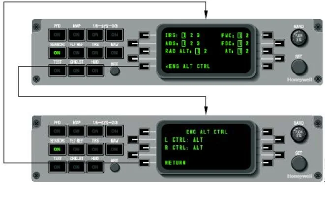
If one engine reverts to alternate LP thrust control, the other engine should be manually selected to LP control in order to maintain symmetric thrust. Manual selection of alternate engine control is accomplished using the Display Controller (DC). The DC Sensor menu contains a Line Select Key (LSK) for engine data on the lower left of the menu. Depressing the engine data LSK results in the display of the ENG DATA menu. The first and second LSKs on the menu, labeled RCTL and LCTL, may be used to select ALT control for the right and left engines. See Section 2B-02-00 for a description of the Display Controller.
You will see this now and then so you should know why it is important and how to deal with it. The FADEC wants to control the engines using EPR. If EPR become unavailable, even momentarily, the FADEC uses an ALTernate means to control the engine: LP (N1). If engine alternate control happens on its own, the so called "soft reversion," you will not get a CAS message but you will see the amber ALT icon next to the engine's LP display. If you have a valid EPR indication you can return the engine to EPR control by toggling the ENG ALT CTRL section on the display controller. Selecting it once turns the amber icon to blue, ALT, the so-called "hard reversion," and gives you the CAS message. Toggling it again removes the CAS message and the icon, and returns the engine to EPR control.
Idle Thrust Management
[G450 Aircraft Operating Manual, §2A-76-30 ¶3.] The engine EEC controls HP rpm when the power lever is positioned to idle. The idle power lever setting has two ranges: low idle and high idle. The EEC will control the engine at the high idle setting if data from the MAUs indicate that the aircraft is in approach mode. Approach mode is indicated if the flaps are set to more than 22°, the Weight-On-Wheels (WOW) system is in the air mode, and the anti-skid wheel speed sensors do not detect wheel rotation. If a data failure prevents the EEC from determining the approach configuration, the EEC will default to the high idle mode. High idle during an approach ensures a more rapid engine response in the event of a go around. The EEC will continue the high idle control mode for five seconds after landing to allow rapid engine acceleration for reverse thrust if needed.
The exact HP rpm setting for both low and high idle is dependent upon pressure altitude, with a minimum rpm setting predicated upon the following engine functions:
Supplying sufficient bleed air to meet pneumatic system and anti-icing requirements
Prevent ice accumulation on the engine fan stage
Maintain the engine-driven generator at operational speed
Operation of the engine handling bleed valves
Indication
You need to worry about engine parameters for start, takeoff, and shutdown. Other than that, the engines pretty much take care of themselves. You might spend your entire G450 career and need to know nothing else. But if they do push you into the "Engine Broke" section of the QRH, you should know How the engine indications are getting to you, Where they are coming from, and What constitutes an abnormal condition.
How the indications are getting to you: PlaneView

[G450 AOM, § 2A-77-10 ¶1.A.] Engine data used by the EEC is shared with the Modular Avionics Units (MAUs) in order to provide flight crew oversight and control of engine performance using visual graphics shown in selectable windows on the cockpit Display Units (DUs). EEC data is supplemented with information from a separate installation that senses vibration levels within the engine in order to diagnose engine health. The following parameters are the primary means of observing engine performance and are shown on every engine display format:
Engine Pressure Ratio (EPR)
Engine Low Pressure (LP) Rotor Speed
Engine High Pressure (HP) Rotor Speed
Turbine Gas Temperature (TGT)
Supplemental engine data related to engine performance but not directly employed in EEC control of engine operation are included in an optional secondary cockpit display format.
Oil Pressure
Oil Temperature
LP Engine Vibration Monitor (EVM)
HP Engine Vibration Monitor (EVM)
Fuel Flow
[G450 AOM, § 2A-77-10 ¶2.A.] The PlaneView™ display system incorporates four Accelerated Graphics Modules (AGMs) capable of generating a large amount of graphic information at a rapid refresh rate for the cockpit displays.
Video: Two DU Synoptics.
You can have both of these pages available to you all the way down to battery power under most conditions. You simply need to use Two DU Synoptics and access the pages through the display controller. The data does, however, come through the MAUs and AGMs and if you have problems with those, you need to use the Standby Engine Instruments available on MCDU #1.
How the indications are getting to you: Standby Engine Instruments

[G450 AOM, § 2A-77-10 ¶2.C.] In the event that a malfunction or failure prevents viewing engine readings on any of the Display Units, a standby engine instrumentation presentation is available on MCDU #1 only. The display is available with only battery power and consists of digital readings of EPR, TGT, LP and HP rpm, Fuel Flow (FF) and Fuel Quantity (FQ). The MCDU presentation is shown in Figure 4. The display is accessible by selecting the menu function key on MCDU #1, then choosing Standby Engine from the displayed menu with the Line Select Key (LSK).
These indications are available down to emergency battery power.
Where the indications are coming from
EPR

[G450 AOM, § 2A-76-30 ¶1.] EPR is defined as the ratio of pressure sensed at the exit of the High Pressure (HP) compressor to the pressure of the ambient atmosphere as sampled within the engine bypass air duct.
[G450 MM, § 77-11-00 ¶1.A.] EPR = P160 divided by P20. The EPR value is the ratio of the total fan duct pressure (P160), to the intake total pressure (P20). The two sources of pressure are supplied to the Engine Electronic Controller (EEC) which calibrates them and calculates a correct EPR value. P20 pressure is measured by three independent Air Data Modules (ADMs) which use aircraft pitot and static sensors. These transmit the data to the EEC which compares the signals and makes adjustments for altitude, air temperature and speed. The corrected value of P20 is changed by the EEC to a digital value. P160 is measured with four rakes installed at equal distance around the forward section of the bypass duct. The rakes, each of which has five nozzles, are installed in the bypass duct radially, so that the nozzles are in line one above the next.
There is a lot of confusion about G450 EPR, including by the Gulfstream manual writers. Let's address the common theories:
Classic engineering: EPR is engine output pressure divided by input pressure. While this might be true under the classic definition of EPR, it has long been discarded in modern turbo fan engines. In the G450, it is not true. Can you, after all, really believe the pressure at the tail pipe is only 67 percent greater than the intake at takeoff power? Or can you agree there is less thrust in the G450 than the GIII, which had higher EPRs?
More about this: EPR.
G450 Aircraft Maintenance Manual: EPR is bypass fan duct pressure divided by ambient air pressure. The maintenance manual has diagrams of the fan duct pressure probes but no pressure probes at all inside the engine itself. The bypass duct pressure compared to ambient air pressure would indeed be an analog of engine performance.
G450 Aircraft Operating Manual: EPR is pressure aft of the high pressure compressor divided by engine bypass air. This is also plausible and would make a good analog of engine performance.
The only thing clear about G450 EPR is that it is not the classic output divided by input metric. I think the AMM is correct but don't know for certain. In any case, you and the FADEC have EPR numbers for high thrust required situations and setting them is straight forward. At any other time the only thing you can infer from EPR is higher numbers mean more thrust.
TGT

[G450 MM, § 77-21-00 ¶ 1.A.] TGT is measured by nine dual-element thermocouples which are connected in parallel by a harness assembly. The thermocouples are installed in nine LP1 Nozzle Guide Vanes (NGV) at equal distance around the front section of the Low-Pressure (LP) nozzle case.
[G450 MM, § 77-21-00 ¶ 2.A.] Each TGT thermocouple has two metal tubes which are brazed together and attached to a mounting flange and terminal head. The tubes are different lengths and each contains a nickel-aluminium (alumel) element, and a nickel-chromium (chromel) element, connected together at the inboard ends. Changes in TGT sensed by the elements are transmitted as electrical signals through the harness assembly to the two channels of the EEC.
LP
[G450 MM, § 77-13-00]
There isn't much written about this but we can infer from the diagram in the maintenance manual that N1 is taken directly from the shaft.
HP

[G450 MM, § 77-12-00 ¶1.A.] N2 is measured by three pulse probes which are installed in the external gearbox. The probes make a magnetic circuit with a phonic wheel which is installed on the shaft of the Permanent Magnet Alternator (PMA). The PMA is installed on the front face of the gearbox and is turned by the HP compressor shaft. As the shaft turns, the teeth of the phonic wheel cause a voltage in the speed probes. The frequency of this voltage is in proportion to the shaft speed and the signals are transmitted to the EEC.
Fuel Flow
[G450 MM, § 73-30-00 ¶1.A.] The fuel flow indicating system uses a fuel flow transmitter to continuously monitor the fuel flow to the combustion system. The transmitter is in position between the Fuel Metering Unit (FMU) and the fuel manifold. The straight part of the tube at the transmitter inlet supplies the fuel at a constant and linear flow. This makes sure that the flow can be accurately measured.
Oil Press
[G450 MM, § 79-33-01 ¶1.] The oil pressure transducer assembly includes two oil pressure transducers and the oil filter differential pressure transducer.
Oil Temp

[G450 MM, § 79-32-01 ¶1.] The oil temperature bulb is installed on the front of the fuel cooled oil cooler at the engine oil outlet.
EVM

[G450 AOM, § 2A-77-10 ¶1.B.] The EVM system provides oversight of the mechanical health of the engines. Since turbofan engines operate at a very high rpm (HP rotor speed is 12,484 rpm at 100%) all rotating components must be very accurately balanced in order that centrifugal effects within the engine do not result is destructive forces. Even small amounts of vibration within the engine could be the precursor of catastrophic damage. The EVM system detects anomalies in engine rotational balance through dual accelerometers mounted side by side on the engine exterior. Only one (primary) accelerometer actively provides signals to the EVM system - the other (secondary) unit provides redundancy and may be selected for signal input in order to confirm abnormal vibration readings. The accelerometers detect vibration as a centripetal force (perpendicular to engine centrifugal force) induced by any out of balance component on the LP or HP rotors.
The vibration is measured in inch/pounds per second and reported via low noise cable connections to the Integrated Engine Vibration Monitor (IEVM) card that is installed in Modular Avionics Unit (MAU) #1. MAU #1 also provides electrical power to the accelerometers either from the Left Essential or Right Main DC bus through the MAU backplane (bus power source depends upon availability).
Since the LP and HP rotors are the only rotating assemblies within the engine and the rpm of each rotor is significantly different (LP rotor speed is 8,393 rpm at 100%) the period or frequency of any vibration can be readily associated one or the other rotors. The IEVM receives signals from the speed probes of each rotor that provide indications to the EEC. The IEVM is programmed to associate vibrational frequencies with rotor speed in order to provide an EVM reading for each rotor.
[G450 MM, § 77-31-00 ¶1.A.] Each engine is monitored by two transducers, one primary and one secondary, installed together on the intermediate compressor case. The transducers are connected with an electrical harness to a Signal Conditioning Unit (SCU) which is installed in the aircraft. N1 and N2 speed signals, and a once per revolution signals are also transmitted to the SCU. The signal from one transducer on each engine is compared to the N1 and N2 speed signals. The SCU makes an analysis of the electrical signals and changes them to a digital value for flight compartment display.
[G450 AOM, § 2A-77-10 ¶5.A.] High EVM indications should not be the sole criteria for engine shutdown. If EVM indications exceed 0.60 for LP and/or HP rotors, first confirm the reading by selecting the secondary accelerometer. If EVM remains excessive, retard the engine power lever to reduce EVM to an acceptable value. If high EVM readings are accompanied by other abnormal engine indications, the engine should be shut down. When operating in icing conditions, high EVM readings may be expected as the engine sheds accumulations of frozen precipitation.
While there are two transducers per engine, they do not monitor the individual spools, HP and LP. Each individual transducer provides information to the signal conditioner unit which adds RPM data to derive separate HP and LP vibration data. Your first response to any abnormal EVM indication should be to switch from PRIMARY to SECONDARY to see if the other transducer, mounted just a few inches away, agrees.
Engine Fuel Temp

[G450 MM, § 77-42-00 ¶1.A.] Fuel temperature is measured with two nickel Resistive Bulb Thermometers (RBT) which are contained in one unit. The unit is installed to an elbow on the fuel outlet of the fuel cooled oil cooler assembly. Thus, the temperature is measured upstream of the fuel filter. There are two electrical connectors on the unit and each RBT is electrically connected to a different channel of the Engine Electronic Controller (EEC).
What constitutes an abnormal indication
EPR
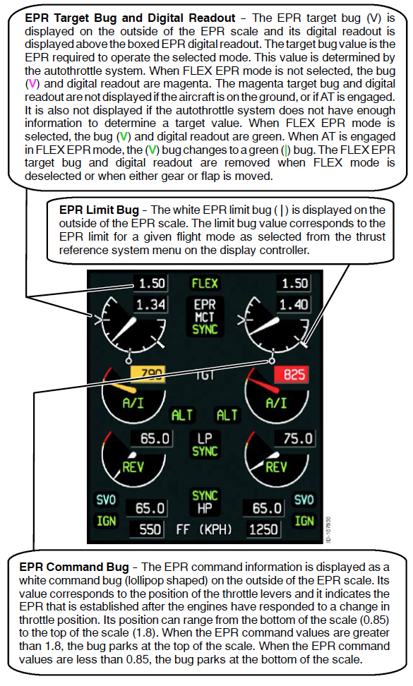
[G450 AOM, § 2B-09-150 ¶2.] EPR Analog Scale -- The EPR arc is an all white scale. The lower end of the arc corresponds to 0.85 EPR. The upper end of the arc corresponds to 1.80 EPR. There are tick-marks every 0.1 EPR starting at 0.9 and going to 1.80. The scale from 1.5 to 1.8 is compressed. EPR Digital Display -- The EPR digital display is located and boxed close to the center of the arc. The digits and box are always white. The digits display EPR data to the hundredths decimal place over a range of 0.00 to 4.00. The range of the pointer is 0.85 to 1.80. When data goes below 0.85, the pointer remains stationary at the lower limit, and the digits show actual EPR value. When the data goes above 1.80, the pointer remains stationary at the upper limit and the digits show the actual EPR value.
The only limitation based on EPR is the G450 AFM, § 1-71-30 requirement: "Minimum acceptable power for takeoff is shown in Section 5: Normal Takeoff Planning."
TGT

[G450 AFM, § 1-71-10]
The maximum TGT prior to ground start is 200°C
The maximum TGT during ground start is 700°C
The maximum TGT during in-flight starts is 780°C
The maximum TGT during takeoff is 800°C
The maximum continuous TGT permitted is 715°C
The maximum "over temp" is 820°C
The FADEC will try to protect you during automatic ground starts but is not infallible. If you inadvertently leave the engine bleed switches, for example, the APU load control valve will close when the engine reaches 20% HP rpm, well before the starter is supposed to cut out. In this condition, the FADEC will not abort the start and you could over temp the engine.
LP

[G450 AOM, § 2B-09-150 ¶2.] LP Turbine RPM Analog Scale -- The LP arc is a color banded scale (white, amber, and red). The lower end of the arc corresponds to 0% RPM and the upper end of the arc to 111% RPM. The LP tach value represented by the 9 o’clock position on the dial, corresponds to 90%. The LP tach values represented by the white/amber and amber/red transition points, correspond to the LP amber line value and the LP red line value that is computed by the FADEC. The scaling of the pointer beyond the 9 o’clock position is based on the LP amber line value and the LP red line value from the FADEC. When the pointer is in the red region, the arc width is expanded to double width and the pointer color changes to match the arc region. When the value exceeds 111%, the pointer parks at the high end of the scale and the digital value continues to display the actual LP value.
LP Digital Scale -- The digital display is located and boxed close to the center of the arc. The digital display is the numerical value of the pointer. The digital display resolution is 0.1% RPM throughout the range. The display range is normally 0% to 163.8% RPM. The digit colors change from white to amber to red as the present value moves into those regions.
[G450 AFM, § 1-71-10]
The maximum LP % rpm for takeoff is 95.5
The maximum LP % rpm for maximum continuous is 95.5
The maximum LP % rpm for overspeed is 96.5
The maximum LP % rpm for reverse thrust is 65.0
HP
[G450 AOM, § 2B-09-150 ¶2.] HP Turbine RPM Analog Scale -- The HP arc is a color-banded scale (white, amber, red). The lower end of the arc corresponds to 0% RPM and the upper end corresponds to 111% percent RPM. The HP Tach value represented by the 9 o’clock position on the dial corresponds to 93%. The HP Tach value represented by the white/amber and amber/red transition points corresponds to The HP amber line value and the HP red line value that is computed by the FADEC. The scaling of the pointer beyond the 9 o’clock position is based on the HP amber line value and the HP red line value from the FADEC. When the pointer is in the amber or red regions, the arc width is expanded to double width and the pointer color changes to match the arc region.
[G450 AFM, § 1-71-10]
The maximum HP % rpm for takeoff is 100.6
The maximum HP % rpm for maximum continuous is 97.5
The maximum HP % rpm for overspeed is 101.6
FF
[G450 AOM, § 2B-09-150 ¶2.] The fuel flow is displayed in a digital readout in a box close to the center of the arc. English units (PPH) or metric units (KPH) are selected at installation with a programming pin. The digits and box are always white. The range of the digital readout is 0 to 9990 PPH (0 to 4530 KPH) and the resolution is 10 PPH (10 KPH).
Oil Press
[G450 AOM, § 2B-09-170] The range of the display is 0 to 300 pounds per square inch (PSI) in 1 PSI increments. The oil pressure digital readout color (white, amber, or red) is determined by the respective engine FADEC and depends on the range that the oil pressure readings fall into. The exception to this is that the digits also turn amber when there is significant difference between the two oil pressure values measured by the FADEC for that engine. If the input is invalid, the oil pressure digits are replaced with amber dashes (-- -- --).
Oil Temp
[G450 AOM, § 2B-09-170] Engine oil temperature information is supplied by the FADEC. The oil temperature digital window is located directly under the engine oil pressure display. The range of the display is --409° to +409° C in 1° degree increments.
EVM
[G450 AOM, § 2B-09-170] The EVM displays consist of two sets of windows labeled LP and HP. The display ranges from 0 to 9.99 in increments of 0.01 IPS. The EVM is inhibited during engine start.
Engine Fuel Temp
[G450 AOM, § 2B-09-170] Engine Fuel Temp values are displayed in a digital readout with a resolution of 1°C. The digits are replaced with amber dashes (-- -- --) when the temperature sensor for the side displayed is invalid.
Exhaust
The G450 thrust reversers are not as effective as other classic Gulfstreams but you are allowed a performance credit for takeoff on wet runways. There is no manual restow switch as can be found on other Gulfstreams. I asked Rolls-Royce about this and here is what they said:
The G450 Thrust Reversers (TR) while not “clam shell” like the GIV TRs still do provide a component of the thrust vector forward. TR design is a careful compromise between efficiency in the forward mode and the reverse mode. It seems that for the G450 the reason for the new design was to incorporate lightweight, low-drag Nordam TRs. On the GIV SP, the reverser linkages are all external whereas on the G450 the engine nacelles are aerodynamically smooth. The Nordam TR design on the G450 has limited outflow area in reverse mode which limits N1 in reverse mode (G450: 65% N1). The N1 limit is determined by both fan flutter limit and the area ratio of outflow area in reverse mode to nozzle area in forward mode.
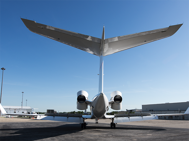
Photo: G450 with reversers deployed, ground spoilers and flaps extended, from Eddie's collection.
[G450 AOM, §2A-78-20 ¶1.] The engine thrust reversers are electrically controlled by the respective engine FADEC in response to flight deck throttle quadrant commands and hydraulically operated by the respective (onside) engine hydraulic system. The engine thrust reverser doors, one on top and another on the bottom of the engine, act in concert to change the direction of engine exhaust gases to aid the braking system in slowing the aircraft. When closed, the doors are fully integrated into the shape of the exhaust section of the engine nacelle. During operation the doors pivot at hinge points, with the aft edges of the top and bottom doors moving inward to mate, forming a blocking surface to interrupt the normal exhaust flow. The forward edges of the doors pivot outward, projecting into the airstream in order to redirect the blocked exhaust flow forward. The thrust reversers are most effective in reducing high groundspeeds in the early phase of landing or an aborted takeoff. The Full Authority Digital Engine Control (FADEC) maintains engine speed at a high idle setting for five seconds to facilitate the immediate use of reverse thrust upon touchdown. Because a malfunction that causes inadvertent opening of a thrust reverser door during flight would cause severe aircraft control difficulties, the FADEC reduces engine power to idle whenever a door exceeds twelve percent (12%) open with forward thrust selected during flight.
These reversers don't "grab" the way they did in the GIV or GV, that is, you don't feel a tug at your shoulder straps when you deploy them. See the photo on the top of the page for the reason why. Whatever the reason, these reversers aren't as effective which gives even more credence to the old adage about Gulfstream reversers: they are most effective at high speeds and useless at low speeds; use as much as you can as soon as you can. (While you can.)
Doors and Seals
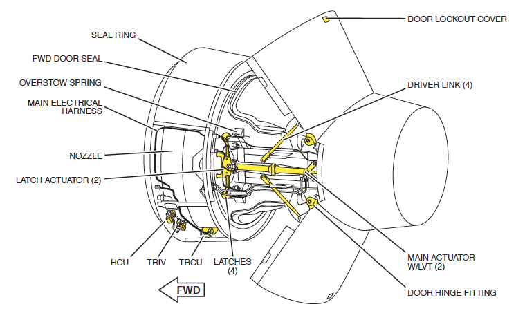
[G450 AOM, §2A-78-20 ¶2.A.] Each engine thrust reverser employs two symmetrical doors that are integral to the engine nacelle exhaust section. The doors are positioned on the top and bottom of the aft section of the nacelle and open vertically to redirect a substantial amount of engine exhaust gases forward when actuated on landing. Not all engine exhaust is redirected due to the concave shape of the doors and because some uninterrupted flow is essential to engine performance. The doors conform to the internal and external shape of the nacelle and are fitted with flexible rubber seals around the perimeter of each door to maintain the integrity of engine exhaust flow when the doors are not in use.
Door Lock Hooks
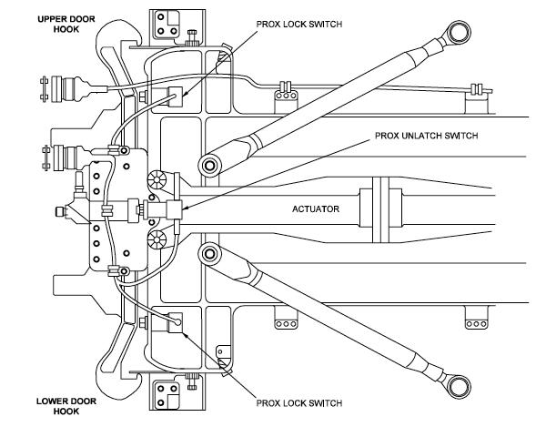
[G450 AOM, §2A-78-20 ¶2.B.] Each reverser door (top and bottom) is locked in the stowed position by two locking hooks, one on the inboard and one on the outboard side of the engine. The locking hooks are essentially movable latch mechanisms, with each hook securing one side of the top or bottom reverser doors. When locked, the hooks engage catches on each reverser door and are held in the closed position by integrated springs. In order for the reverser doors to deploy, the spring force holding the hooks in the closed position must be overcome by hydraulic pressure routed through an electrically controlled unlatch valve. The unlatch valve is pressurized to release the hooks as part of the reverser deployment sequence controlled by the FADEC on each engine. Once the hooks have released and are free of the catches, hydraulic pressure is maintained on the unlatch valve to overcome the hook integral spring pressure that forces the hooks to locked position.
The doors are locked in place only by the pressure of mechanical springs. It takes hydraulic pressure to unlock the hooks.
Hydraulic Actuators
[G450 AOM, §2A-78-20 ¶2.C.] The hydraulic reverser door actuators of each engine are powered by the corresponding side hydraulic system: left engine by the left hydraulic system, right engine by the right system. There is no provision for using an alternate hydraulic system to power the reversers since hydraulic pressure loss would most likely be due to a failure of the associated engine. The outboard actuator moves the outboard side of both the top and bottom reverser doors, with the inboard actuator moving the corresponding inboard side of the two doors. The actuators act in concert to provide symmetrical door operation. Each door actuator moves in two directions: forward to extend the doors to the deployed position and backward to stow the doors in the faired position. Hydraulic pressure is routed to the appropriate side of the door actuator by a Directional Control Valve (DCV) in response to electrical commands to the Hydraulic Control Unit from the engine FADEC in response to the reverse levers mounted on the cockpit power levers. Driver links connect the actuators to the respective doors with hinge points translating the forward and back movement into up and down forces to open and close the hinged reverser doors.
Isolation Control Unit
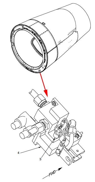
[G450 AOM, §2A-78-20 ¶2.G.] The Isolation Control Unit (ICU) is an electronic installation that governs the flow of hydraulic power to each Thrust Reverser Control Unit (TRCU) by operation of a solenoid-driven isolation valve. The engine EEC employs the ICU in response to reverse lever commands to power the operation of the reversers and to act as a safeguard by interrupting hydraulic power when forward thrust is commanded. The ICU also monitors hydraulic pressure while the thrust reversers are operating in order to forward to the EEC an indication of low pressure that would prevent the thrust reverser from operating.
Hydraulic Control Unit
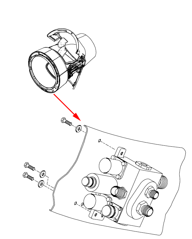
[G450 AOM, §2A-78-20 ¶2.H.] The Hydraulic Control Unit (HCU) contains solenoid operated hydraulic valves that direct on-side hydraulic pressure to latch / unlatch actuator for the door locking hooks and to the correct side (deploy or stow) of the door hydraulic actuators.
Thrust Reverser Control Unit
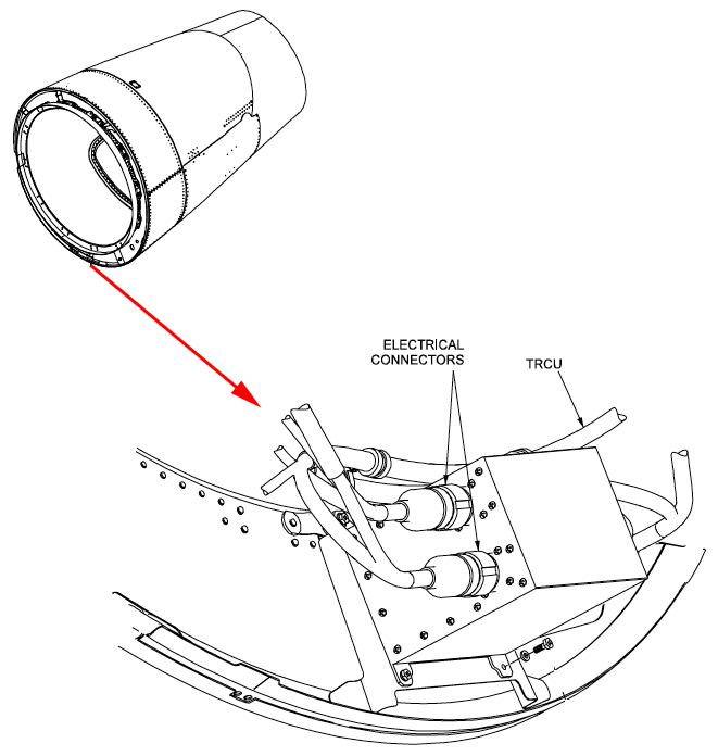
[G450 AOM, §2A-78-20 ¶2.I.] The TRCU contains cards that operate solenoid valves in the HCU to control the flow of hydraulic fluid to the thrust reverser actuators and hook latching mechanism. Once the ICU has provided hydraulic pressure, the TRCU operates valves directing the hydraulic pressure to the actuators in the correct sequence to operate the reversers in response to cockpit reverse lever commands: to unlock the locking hooks and deploy the reversers or to stow the reversers and lock the locking hooks.
Thrust Reverser Lockout
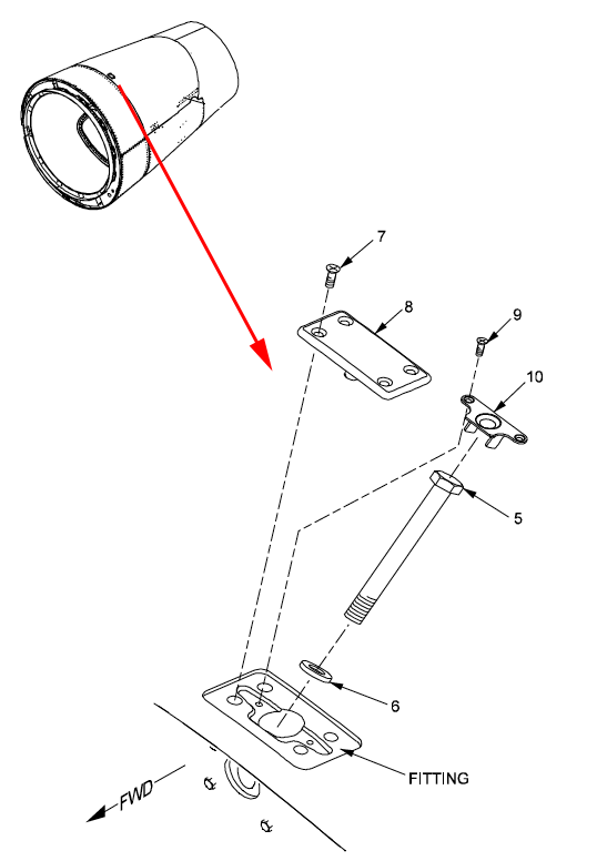
[G450 AOM, §2A-78-20 ¶2.K.] The thrust reversers incorporate a means to mechanically prevent the doors from operating in order to dispatch an aircraft with a malfunctioning reverser system. An access door is provided on the underside of each thrust reverser, adjacent to the isolation valve, in order for a pin to be inserted safetying the isolation valve closed, preventing hydraulic pressure from operating the reverser doors. Once the pin has been installed, a red cover with a protruding indicator seals the access door and furnishes a visual indication that the isolation valve is mechanically locked in the closed position.
The thrust reverser lockout procedure is given in the QRH (NG-49) and the AOM (09-03-10) "to enable the flight crew to assist and supervise ramp service personnel when the aircraft is away from its fixed base of operations." Besides having to deactivate the isolation valve, you need to install inhibition bolts on the top and bottom of the engine. They aren't easy to get to, you will need a ladder and a mechanic who isn't afraid of heights. Taking the inhibition bolt covers requires a razor blade and some patience. I've done this once and it isn't as easy as it was in earlier Gulfstreams. Don't try this yourself!
Thrust Reverser Operation
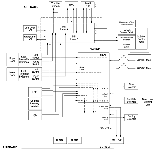
[G450 AOM, §2A-78-20 ¶3.] Thrust reverser operation is controlled by the FADECs on each engine in coordination with cockpit thrust lever position and safety signals from aircraft systems. A typical reverser deployment sequence includes the following events:
The aircraft WOW system and/or anti-skid wheel sensors provide the EECs with a valid signal indicating that the aircraft is on the ground
The flight crew retards the power levers to idle, then pulls up and aft on the reverse levers
The EEC sets the interlock detent on the reverse levers to prevent further lever movement until the thrust reverser doors have deployed at least 12.5%
The EEC maintains engine speed at high idle for five seconds
The EEC signals the Isolation Control Unit (ICU) in the reverser hydraulic system to open, routing hydraulic pressure (left system to left engine, right system to right engine) to Hydraulic Control Unit (HCU)
The Thrust Reverser Control Unit (TRCU) directs the correct solenoid valve in the HCU to operate the latch / unlatch actuator to release the door locking hooks and to port hydraulic pressure to the deploy side of the door actuators
The TRCU initially routes hydraulic pressure to the retract or stowed side of the door hydraulic actuator, forcing the door forward and compressing the rubber seal around the door to enable the catch on the door to clear the door locking hooks that are being held open by hydraulic pressure
After the door locking hook has cleared the latch, the TRCU pressurizes the extend, or deploy, side of the reverser door actuator
The reverser doors open, with position monitored by the LVTs. The EEC releases the reverse lever interlock detent when the doors are 60% deployed
The reverse levers are free to move up and aft and the EEC controls engine Low Pressure (LP) rotor speed in response to cockpit reverse lever commands in the range of idle to full reverse. Maximum reverse thrust is limited to 60% N1 and linearly reduced from maximum to 55% when aircraft speed slows from 60 knots to 50 knots.
When the use of reverse thrust is no longer required, the doors will return to the stowed position through action of the same elements. A typical door retraction involves the following sequence:
The reverse levers are returned to the down or stowed position
The position switch on the reverse levers signals the EEC to pressurize the stow or retract side of the door hydraulic actuators through action by the TRCU, while simultaneously reducing engine power levels to idle
The hydraulic actuators stow the reverser doors, moving them first to an extended stow position, compressing the rubber seals around the door openings to allow the door locking hooks to ride over the door catches. When hydraulic pressure on the latch / unlatch actuator is released, the lock hooks drop into position, securing the door catches.
After the reverser doors are fully stowed as sensed by the EEC from signals from the proximity switches on the locking hooks and unlatch actuator, the ICU shuts off hydraulic power to the reverser components
Performance
[G450 AFM, §5.2 - 2] Field Length Limited Performance. No reverse thrust credit was taken for accelerate-stop distances computed for dry runways; however, the use of reverse thrust is recommended to reduce the braking distance and the kinetic energy absorbed by the brakes. Wet runway accelerate-stop distances are calculated assuming the deployment of one or both thrust reversers.
Reversers always help but you only get credit for them when it comes to takeoff on a wet runway. No credit is given for landing, wet or dry.
Limitations
[G450 AFM, §1-78-10]
Cancellation of reverse thrust should be initiated so as to be at the reverse idle position by 60 KCAS.
There are several theories as to why: (1) at slower speeds the reversed airflow will damage the flaps, (2) engine compressor stalls, (3) tail "blanking" whereby the forward airflow of the engine prevents airflow over the vertical fin and hence a loss of directional control, and (4) tail pivot whereby the nose can be lifted off the ground. I've asked an engineer at Rolls Royce who told me: "The N1 limit is determined by both fan flutter limit and the area ratio of outflow area in reverse mode to nozzle area in forward mode."
Use of idle reverse thrust is available for taxi purposes without time limit.
The thrust reversers shall be deployed and stowed at least once every 100 hours.
If in an emergency, reverse thrust is used to bring the airplane to a halt, record and report such an operation for maintenance action.
Use of thrust reverser(s) for power back is not approved.
Dispatch with inoperative thrust reverser(s) on a wet runway requires that the available runway length be reduced by 600 feet or the accelerate-stop distance be increased by 600 feet.
Oil
Everyone knows how to tell the difference between a GIV and G450 looking head on: the FLIR camera. From the left or right is easy too: the engine cowls. From the right you have the TROV. What about from the rear? That's easy too, the G450 is the one with the trail of oil on the bottom of each cowl.
The only issues you should really have with oil on this aircraft is servicing it at least every 14 hours or cleaning if off the bottom of the cowls. Servicing the oils, however, isn't as straight forward as many think.
See Servicing, below.
[G450 AOM, §2A-79-10 ¶1.] Pressurized oil is supplied to the engine bearings and accessory gears to provide lubrication and cooling. Each engine has an individual oil tank integral to the accessory gear box. The engine oil pump, mounted on and driven by the accessory gear box, pressurizes oil drawn from the tank and supplies the engine bearing compartments and the accessory gearbox through distribution lines. Scavenge pumps downstream of the bearings and gear box return oil back to the tank through a common return line. The oil supply lines are vented to the atmosphere through a breather opening to promote lubrication flow, with a breather separating the resulting air / oil mist, retaining oil in system lines and porting air overboard.
Oil Tank

Figure: Oil tank, from G450 MM, §79-10-00, figure 1.
[G450 AOM, §2A-79-10 ¶2.A.] The oil tank is located below the oil cooler on a bracket at the accessory section of the engine. The oil tanks for both engines are identical, however since the tanks are mounted differently - the right engine tank at the eleven o’clock position when viewing the engine from the front and the left engine tank at the one o’clock position when viewing the engine from the front - the capacity of each of the tanks differs slightly. Tank capacity of the right engine is 15.5 U.S. pints, the left engine tank holds (14.5 U.S. - however both hold 10.8 U.S. pints of usable oil.
An oil level sight glass installed on the tanks at the outboard side of the engine permits direct observation of tank quantity. The sight glasses are calibrated and color-coded for the specific engine installation: the left engine sight glass has a red scale, the right engine a green scale. If the oil quantity requires servicing, oil can be added directly to the tank through a filler tube, a pressure fill connection for an external tank or through the engine oiler located in the tail compartment.

Figure: Tay 611-8C engine oil tank, from G450 AOM, §09-02-00, figure 6.
The left engine's scale is on the left, the right engine's scale is on the right. The engines are hung on the airplane at angles which doesn't give you a lot of viewing space for the left engine. You can only see down to minus 2 and if you have a mirror you might be able to make out minus 3.
Oil Quantity Transmitter
Figure: Oil quantity transmitter, from G450 MM, §79-31-01, figure 401.
[G450 AOM, §2A-79-10 ¶2.B.] An oil quantity resistance-type probe in the tank provides data to the FQSC software. The resistance of the probe varies with the amount of oil in the tank causing the voltage of a reference signal supplied by the FQSC to change accordingly. The voltage is translated by the software into a reading in pints supplied to the MAUs. The MAUs forward quantity information for cockpit display on the Ground Service 1/6 window.
Though Rolls-Royce says the only accurate measure of oil quantity can be made from the oil sight glass on the engine, you can get a feel for how accurate the electronic display is by making periodic comparisons. On our airplane, for example, they are dead on.
Oil Pump

Figure: Oil pumps assembly, from G450 MM, §79-20-00, figure 2.
[G450 AOM, §2A-79-10 ¶2.C.] The oil pump is located on and driven by the accessory gearbox. The pump is a positive displacement unit that operates whenever the engine begins to rotate, drawing oil from the engine tank and pressurizing the supply lines for distribution to engine components. The pump incorporates a pressure relief valve that opens at 200 psi and returns excess pressure to the pump inlet.
Fuel Cooled Oil Cooler (FCOC)

Figure: Assembled tubes of combined fuel cooled oil cooler, from G450 MM, §79-22-01, figure 402, sheet 1.
[G450 AOM, §2A-79-10 ¶2.D.] The FCOC is located between the oil pump and the oil filter. The oil cooler is a heat exchanger that uses hot engine oil to warm fuel drawn from the wing tanks prior to entering the engine fuel metering unit. The lower fuel temperature is increased and the warm oil temperature reduced in the heat exchange process. During cold weather starting, a pressure relief valve on the heat exchanger bypasses oil around the cooler above 50 psi to prevent further increases in oil viscosity.
Oil Temperature Transducers
Figure: Oil temperature bulb, from G450 MM, §79-32-01, figure 401.
[G450 AOM, §2A-79-10 ¶2.E.] Dual oil temperature transducers are mounted in the oil return line to the tank. The temperature transducers are very similar to the pressure transducers, with only the transducer associated with the active FADEC channel operating to supply temperature data. The transducer measures a change in resistance to a reference voltage supplied by the FADEC caused by temperature variation. The voltage difference is interpreted by the FADEC as oil temperature and communicated to the MAUs for use on cockpit engine display windows.
Oil Filter Assembly

Figure: Pressure filter, from G450 MM, §79-20-00, figure 4, sheet 1.
[G450 AOM, §2A-79-10 ¶2.F.] A filter installed on the oil pump removes any debris in the oil prior to delivery to engine components. The filter incorporates a differential pressure switch that monitors oil pressure at the filter inlet and pressure at the filter outlet. If debris collects within the filter restricting oil flow through the filter, a pressure differential will be detected by the switch. If a pressure differential reaches approximately 18 psi, the switch will indicate to the EEC an impending blockage of the filter. At approximately 30 psi differential the oil will bypass the filter and a mechanical “popup” indicator will activate signaling the bypass.
There used to be a Transit Checklist that required this DPI be inspected at least every 14 hours. That checklist has been deleted and Rolls-Royce confirms the check is unnecessary. (See "Oil DPI" below for more.)
Magnetic Chip Detectors

Figure: Magnetic chip detector, from G450 MM §79-21-05, figures 401 and 402.
[G450 AOM, §2A-79-10 ¶2.G.] Magnetic detectors are installed in the two scavenge pump return lines to monitor the presence of metallic particles in the oil supply. The detectors use magnetic force to attract any metallic debris in the oil supply. The detectors are periodically examined for evidence of particle accumulation that may indicate engine wear or deterioration.
Oil Pressure Transducers
Figure: Oil pressure transducer, from G450 MM §79-33-01, figure 401.
[G450 AOM, §2A-79-10 ¶2.H.] Engine oil pressure is measured by two variable resistance transducers that sense the oil pressure supplied to the engine bearings and accessory gears. (Only one of the transducers is active at a time - the dual installation provides a transducer for each FADEC control channel.). Pressure is measured by the transducers as a change in resistance to a reference voltage supplied by the engine FADEC. Oil pressure reported to the FADEC is forwarded to the MAUs for formatting on cockpit engine displays.
Oil Replenishing System

Figure: Oil replenishing system, from G450 MM §79-13-01, figure 401.
[G450 AOM, §2A-79-10 ¶2.I.] An oil replenishing system, powered by the ground service bus, is located on the left side of the aircraft tail compartment. The system includes a reservoir and quantity gage that can be used to fill the engine oil tanks if servicing is required (the system is also used to service the APU oil tank). The reservoir holds 14 pints of engine oil when full and has a sight gage to indicate the amount of oil remaining in the reservoir. The reservoir may be filled through a removable cap on top of the reservoir tank.
The control panel for the replenishing system contains a digital engine oil quantity gage and a manual selector valve that is used to direct the output of an electric pump that transfers oil from the reservoir to the designated engine oil tank.
The quantity signal is provided by the FQSC interface that also supplies data to the Ground Service 1/6 window on the cockpit displays. The quantity indications on the display screen show the engine oil tank levels (and APU oil state). If the tank is full, a digital text indication of FULL is shown; if the tank oil level is at or below the minimum usable level, a text indication of LO is displayed. Readings between FULL and LO are shown in pints below the full level, with a resolution to 0.1 of a pint.
The quantity indicated by the electronic readout at the oil replenishing system is the same provided to the Ground Service 1/6 window in the cockpit. The only true indication of oil tank level is at the engine's sight glass.
Oil Servicing
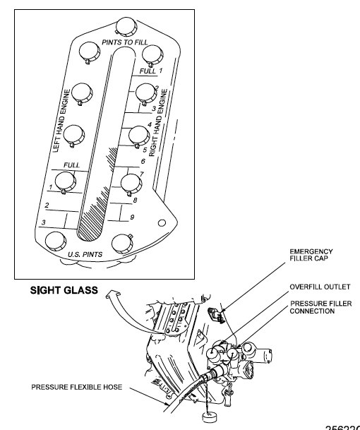
Figure: Tay 611-8C engine oil tank, from G450 AOM, §09-02-00, figure 6.
[G450 AOM, §09-02-20] CHECK ENGINE OIL QUANTITY BETWEEN FIVE (5) AND THIRTY (30) MINUTES AFTER SHUTDOWN. DO NOT SERVICE OIL ON A COLD ENGINE. IF IN DOUBT, RUN ENGINE AT IDLE FOR TEN (10) MINUTES. RECHECK OIL LEVEL TO DETERMINE IF ENGINE NEEDS OIL SERVICE. FAILURE TO FOLLOW THESE PROCEDURES COULD LEAD TO OVERFILLING OF OIL TANK AND/OR DAMAGE TO OIL PUMP.
The Aircraft Operating Manual is wrong here. Rolls-Royce says the engine oil quantity must be checked between 15 and 30 minutes.
[G450 EIS Newsletter, Volume 20, p. 6] Since the tank is "active" during engine running it is essential that, as per the AMM, the oil level should only be checked 15 to 30 minutes after shut down otherwise the incorrect quantity of oil may be added to bring the engine to the required level. The most common scenario of mis-servicing is to check the quantity outside of the 15 to 30 minute range, note that the quantity is reading low, and then add oil. This can result in over servicing. Also, failure to heed the AMM caution of maintaining a 4-5 second delay between adding oil and reading the quantity indication can also lead to an over servicing condition.
There is an idea out there that this system can overfill the engine. That was true in the GIV where the system was purely mechanical. But not so with the G450, provided you measure the quantity inside the 15 to 30 minute window:
[G450 EIS Newsletter, Volume 20, p. 6] The G350/G450 aircraft features a Remote Oil Fill system permanently coupled to the engine through a Remote Oil Fill Valve mounted on the rear of the Oil Tank such that the valve opens as oil is pumped from the aircraft mounted reservoir and then remains closed during normal engine operation. The engine Oil Tank contains an Oil Quantity Transmitter which provides the signal to the digital indicator on the reservoir and for the flight deck indication. The ROF system is designed such that while selected on (via the switch) the pump at the reservoir will flow oil to the engine oil tank and stop when the tank is full as sensed by the Oil Quantity Transmitter.
Quantity
[G450 EIS Newsletter, Volume 20, p. 6] The Maintenance Manual specifies that oil should be added until the Oil Qty indicator displays FULL. This is a regulatory requirement to ensure that long range operation of the engine is achieved even under worst case operating and engine conditions. Many operators choose to service to a level of 1 or 2 pints below FULL because this level seems to be the level that the engine settles into under normal operation.
I am a bit conflicted about this. The book says full and that's what I should be doing. But when we've done this the oil is quickly dispensed on the next flight, usually all over the cowl. I'm still debating this.
Burn rate
[G450 EIS Newsletter, Volume 20, p. 6] Oil consumption on the Tay family of engines is normally well below the AMM limit of 0.75 US pints per hour. However the engine depends on air pressure to seal the bearing chambers and at Ground Idle this air pressure is relatively low and hence the sealing efficiency is reduced. As a result it is not unusual to see some oil dripping from the LP Cooling Air Outlet initially on start up, especially if there has been a long time at Idle prior to the previous shut down. This dripping is consistent between the -8 and -8C engines.
Checking Oil from the cockpit or the aft equipment readout
Can you use the readout from the cockpit 1/6 page or the electronic readout in the aft equipment bay? Is it okay to use these and skip the sight glass on the engines? It appears the answer is yes, provided . . .
[G450 EIS Newsletter, Volume 20, p. 6] While the oil quantity system has proved to be very reliable, as with any system there are tolerances. It is suggested that customers carry out a "one-time" check to identify the reading on the reservoir indicator when the sight glass is showing the level to which the engine will normally be serviced. This indicated quantity should then be used to terminate servicing from the control panel on the reservoir in the equipment bay.
Checking the Oil at the Sight Glass
[G450 AOM, §09-02-20]
Engine oil level check using oil tank sight glass: open engine oil servicing access panel, if oil level is below lower FULL mark, fill oil tank.
Note there are two scales, one for the left and one for the right. The scales are needed since the tanks are mounted in different positions on each side. Simply read the left scale for the left engine and the right scale for the right.
Checking and Servicing the Oil at the Remote Filler Panel
Energize the ground service bus
Place Remote Servicing Panel switch to ON, verify L ENG, R ENG, and APU oil quantities
Place oil replenisher selector valve to position on engine to be serviced
Place FILL/TEST switch to FILL and hold, verify oil replenisher begins operating and desired engine oil quantity begins to rise
Continue holding FILL/TEST switch until selected engine oil quantity reaches FULL level OIL QTY indicator, release switch
Oil DPI Check
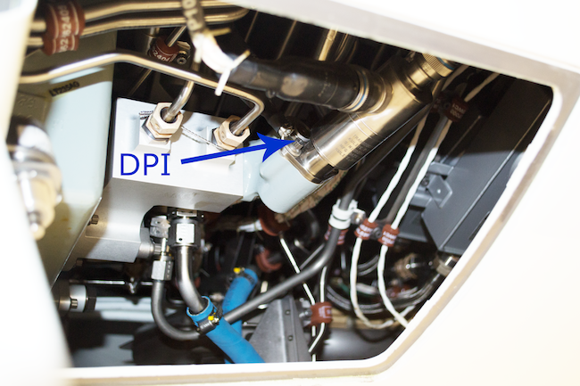
Photo: Oil DPI, from Eddie's aircraft.
The G450 used to have a procedure called the G450 Transit Check that required you to examine the oil filter differential pressure indicator on each engine at the termination of day's last flight or at intervals not exceeding 14 hours cumulative flight time. There is no longer a published requirement to check these DPIs.
Why Time Matters When Checking the Oil
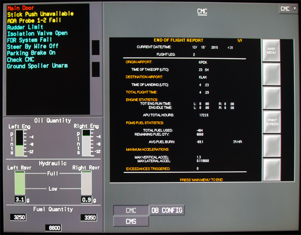
Figure: G450 Oil Quantity Synoptic, from Eddie's airplane.
There is an idea that the 30 minute criteria is a minimum, that you can get an accurate oil indication anytime after 30 minutes. That is wrong. The photo on the top of this page may be an example of what can go wrong. Here is my theory on what led to that photo:
Both engines were serviced to -2 pints, as is the flight department's practice. (While Rolls-Royce says to service to full, most G450 operators note this causes the engine to expend 2 pints on the next cycle, no matter the flight duration.)
The aircraft flew a series of trips totaling 6 hours where the oil was not checked until the last flight of the day, and then it wasn't checked until 1 hour after engine shutdown. At that point it was noted the left engine was at -4 pints so 2 pints were added. The actual level, had the check been made properly, was probably -6. (Using 4 pints after 6 hours and several flights would be well within the 0.75 pints/hour maximum.)
The next day the flight crew noted the oil was serviced to -2. They didn't realize it was probably at -4. They flew two legs, totaling 7 hours. They checked the oil during the correct time frame and were alarmed to see a reading of -8.
The second crew thought they had burned 6 pints in 7 hours, or 0.86 pints per hour, exceeding the maximum. In fact, they had actually burned only 4 pints for a burn rate of 0.5 pints per hour, well within the maximum allowed.
Limitations
[G450 AFM, §1-79-10, 1-79-20]
Oil inlet temperature:
Minimum for Starting: -40°C
Minimum Before Increasing Power: -30°C
Maximum Temperature: +105°C
Maximum (15 minutes) Transient: +120°C
NOTE: External heating will be required to raise oil temperature to -40°C for cold weather starting. If oil temperature is less than -30°C, the engine should be idled until at least -30°C temperature is reached.
Oil Pressure:
Minimum at Idle: 17 psi
Minimum acceptable for takeoff (at Takeoff Power): 30 psi
Minimum to Complete Flight:
At MCT (97.5% HP): 25 psi
At 86% HP: 20 psi
At 76% HP: 16 psi
Starting
G450 start procedures seem complicated but they are not. Much of the nomenclature is confused because it comes from the GV which has multiple start options. We have just the following:
Automatic ground start for all normal ground operations. (Uses the "START" switch.)
Alternate ground start which only comes into play if the "START" switch is broken. (Uses the "CRANK" switch.)
Windmilling start.
And that is it. You can accomplish either ground start procedure using the APU, an external air cart, or a crossbleed from the opposite engine. Oh yes, you could use the starter in the air and two hydraulic abnormals call for this. But it isn't given in our manuals as a way to start the engines.

What follows is a description of this system, taken from the G450 Aircraft Maintenance Manual (AMM) and Aircraft Operating Manual (AOM). You have to be careful reading these, however, as they are filled with errors.

[G450 AOM, § 2A-80-10 ¶1.A.] The engine is equipped with an air turbine starter mounted on the accessory gearbox. The starter is powered by pressurized pneumatic air provided by the Auxiliary Power Unit (APU), the other operating engine or by an external air cart. Airflow to the turbine starter is controlled by the Starter Air Valve (SAV). When the SAV opens, pneumatic air is directed onto the turbine blades of the starter causing the starter to turn. Gears within the starter transmit starter rotation to the drive shaft of the accessory gearbox. Rotation of the gearbox turns the High Pressure (HP) engine rotor assembly, inducing airflow through the engine and consequently causing rotation of the Low Pressure (LP) rotor. When the engine reaches sufficient speed, the Electronic Engine Control (EEC) energizes the engine ignitors and provides fuel flow to the nozzles in the engine combustion chamber to start the engine. After combustion has been initiated, the engine HP and LP rotors accelerate and rotation of the turbine starter is no longer required. The SAV closes, blocking air to the starter, and the starter is disengaged through the action of an internal clutch in the starter gear assembly that actuates when engine HP rotor speed exceeds starter turbine speed.
The starter is connected to the high speed accessory gearbox which during start turns the N2 spool. I've heard you can start the engine with the N1 spool frozen and it operates okay until it eats itself alive. True or not, it makes good sense to ensure you have good rotation on both spools before moving the fuel switch to RUN.
Starter Air Valve

[G450 AOM, § 2A-80-10 ¶2.A.] The Starter Air Valve (SAV) is located on the rear section of the engine at the juncture of lines connecting engine bleed valves to the aircraft pneumatic system. The valve is directly connected to the aircraft bleed air manifold in order to receive pressurized air from the APU, the other engine when it is operating or from an external air source. The primary element of the SAV is a butterfly valve controlled by a solenoid. The valve is normally held in the closed position by an integral spring and the pressure of air within the aircraft pneumatic supply manifold directed against the valve. When the SAV is commanded open by the EEC during engine start, the electrical open signal is provided to the valve solenoid that subsequently opens an internal chamber on the SAV to admit pneumatic manifold air to the open side of the valve. Pneumatic pressure overcomes the loading of the integral spring and moves the butterfly valve open, admitting pressurized air into a duct running forward on the engine to the starter turbine. The rate of valve opening is controlled to prevent a rapid spin-up of the starter.
When the engine has reached sufficient rpm and the starter turbine is no longer required, the EEC signals the solenoid on the SAV to close the air passage holding the valve open and spring pressure closes the SAV.
If an electrical failure of the SAV solenoid prevents normal engine starting, a procedure is provided for manually opening the SAV to power the starter turbine in order to dispatch the aircraft.
This procedure is quite a bit more complicated than it was in earlier Gulfstreams and you no longer have the option of "exercising" the valve. The AMM and AOM differ on what the valve does in the absence of electrical power but agree the valve requires air pressure to move. If you force the valve without air pressure you can hear ratchets inside the valve click.
For more on how to manually move the valve, refer to G450 Manual Starter Valve Operation.
If a failure during an engine start prevents the SAV from closing at the normal starter cutout HP rpm, the flight crew must shut off the bleed air supply to the SAV to prevent damage to the starter air turbine. The abnormal condition is indicated by the continued display of the L SVO or R SVO (left or right start valve open) text icon on the Engine Start 1/6 window after the engine has reached idle rpm.
Air Turbine Starter

[G450 AOM, § 2A-80-10 ¶2.B.] The air turbine starter is mounted on the engine accessory gearbox at the forward section of the engine. Pneumatic pressurized air from the SAV is routed to the starter through a dedicated duct. When the SAV opens to drive the starter, air is directed against the blades of the turbine, rotating the starter. Air from the starter is exhausted through an outlet on the bottom of the engine cowling. The starter turns an attached gear assembly that is connected to the drive shaft of the accessory gear box, rotating the engine HP rotor. A sprag clutch is incorporated in the starter gearing in order to disengage the starter when engine rpm exceeds starter drive speed, normally at forty-one percent (41%) N2. At starter disengagement, the EEC closes the SAV and the starter turbine spins down through the frictional forces of the gear assembly.
The engine bleed valve switch must be off when starting the engine using APU bleed air. APU Load Control Logic will prematurely shut off APU air well before the engine reaches normal starter cutout speed and a hot start will probably result. The FADEC will not protect you.
See: APU Load Control Logic.
Starter Ratchet — Static

There is a bit of confusion in the manuals about the engine's starter. The following is pieced together from the FlightSafety G450 Maintenance Training Manuals, Ch. 80.
The drawing shows a cross section of the starter when the engine is at rest and no air pressure is applied to the starter valve.
The inner gear with the ratchet teeth is attached to the starter.
The outer pawl carrier is mechanically attached to the HP gear box. (When the HP spool spins, so does the pawl carrier.)
The pawls are spring loaded to the inner position, making contact with the starter ratchet. Starter Air Valve pressure is also used to force the pawls inward.
Starter Ratchet — Engaged

When the starter air valve is opened and air pressure is provided to the starter, the starter ratchet (the inner gear shown on the diagram) spins.
Since the pawls are engaged by the starter ratchet teeth, the pawl carrier also spins.
The pawl carrier is connected to the HP spool, which also spins as a result.
Starter Ratchet — Disengaged

At a speed just below starter cutout, the centrifugal force is great enough to overcome the spring pressure on the pawls.
When the Starter Air Valve closes, the starter ratchet stops rotating while the pawl carrier continues to rotate with the engine.
This allows the force to be removed from the pawls which then retract out of the starter ratchet teeth, causing the pawls to disengage and allowing the starter to stop rotating.
Normal Engine Starting

[G450 AOM, § 2A-80-10 ¶3.A.] In normal engine starts, the EEC controls the operation of the SAV and initiates ignition and fuel flow in the engine combustion chamber according to a schedule related to HP rpm. The EEC will close the SAV and shutoff ignition at approximately forty-one percent (41%) N2 (HP) rpm. If an anomaly occurs during the start, the EEC will discontinue the starting process and the FADEC will signal the condition to the Modular Avionics Units (MAUs), prompting the display of an amber “L-R Autostart Abort” CAS caution message. See Engine Start.
Alternate Engine Starting
[G450 AOM, § 2A-80-10 ¶3.B.] If operational circumstances require that the flight crew assume direct control over the engine starting procedure, an alternate starting procedure is provided. The procedure is appropriate when tailwinds exist or when other circumstances dictate that the engine should achieve maximum starter rpm prior to the initiation of combustion. During an alternate engine start it is the responsibility of the flight crew to monitor engine parameters since the EEC will not automatically interrupt the starting process. See Engine Start.
The alternate ground start procedure (G450 QRH NG-4) differs from the normal engine ground start procedure (G450 QRH NC-8) only in that you use the CRANK MASTER instead of the START MASTER and you select continuous ignition prior to pressing the START button. You will have to monitor the start more closely since you will not have FADEC auto abort capability. Why would you want to do this?
The AOM says for "operational circumstances," "tail winds," or "other circumstances." The only case I can think of is if the START MASTER switch is broken. In the case of a tailwind, you can use the START MASTER and simply delay selecting the fuel switch to RUN until maximum cranking rpm.
Engine Cranking
[G450 AOM, § 2A-80-10 ¶3.E.] The engine starter may be used to rotate the engine LP and HP sections without starting the engine. The MASTER CRANK switch on the cockpit ENGINE START panel enables EEC operation of the SAV but inhibits EEC operation of ignition and fuel flow to the combustion chamber. Cranking the engine may be necessary to reduce engine temperature prior to start, to expel accumulated fuel from a previous unsuccessful start, or for maintenance troubleshooting procedures.
Starter engagement for cranking purposes must be counted as an engine start cycle under the starter duty cycle limitations.
In the case of needing to reduce engine temperature prior to start, you might consider what the GV crowd calls a "rotor bow" start. Simply conduct a normal ground engine start and delay moving the fuel control switch to RUN until the TGT is below 200°C. You have a 3 minute starter duty cycle and I've never seen this procedure take more than 45 seconds.
Do not use this hybrid "rotor bow" procedure if you have to expel accumulated fuel. It may take several crank cycles to get rid of all the fuel. If you use the tail camera you can see fuel spray out the tail pipe. I would, in this case, use a crank cycle until the fuel spray stops, then stop the crank and wait for 0% rpm and then try a normal engine start.
Automatic Air Starting

[G450 AOM, § 2A-80-10 ¶3.C.] As part of the supervisory functions of the engine FADEC, the EEC will automatically attempt to restart an engine that flames out or fails during flight, provided that the failure is not associated with a recognized abnormal condition (for instance, an engine fire). The EEC restart attempt involves unloading the engine by opening the engine handling bleed valves and supplying continuous ignition to the combustion chamber. If the restart attempt is not successful, the FADEC will prompt the display of the amber “L-R Autostart Abort” CAS caution message.
See Engine Start.
Windmill Airstart
[G450 AOM, § 2A-80-10 ¶3.D.] If the engine starter is not used to increase rotor speed in attempting to restart an engine, an alternate method employing an increase in airspeed at an altitude below twenty-five thousand (25,000) feet is available. The procedure uses additional airflow through the engine to increase engine rotor speed to support a restart.
See Engine Start.
The AOM is confusing here because it was cut and pasted from the GV/G550 manual where the windmill airstart is a secondary means to start the engine while inflight. It is our primary means and a bit simpler. We shoot to have at least 250 knots but will not suffer a start abort if we go below a target speed, as will the GV/G550. There are parts of our manuals that refer to 200 knots as the minimum windmilling speed, that too comes from the GV/G550. Our minimum is as shown on the graph in the AOM limitations section: 250 knots. The graph in the AOM systems section is wrong.
The Chips are Down Start
The book gives you several options from altitude to your inevitable landing with or without the engine turning. But what if you run out of altitude and airspeed for the book's only option of a windmilling start? Can you use the starter? Sure, the plumbing is there. Don't believe it? Look up the procedure for Right Engine Failure and Complete Left/Auxiliary Hydraulic Failure as well as Left Engine Failure and Right Hydraulic Failure. Both these procedures allow the engine starter to be used to generate hydraulic pressure.
Limitations
[G450 AFM, § 1-80-10] The starter duty cycle is:
Three (3) start cycles with a maximum of three (3) minutes per cycle.
Delay 15 seconds between start cycles. After three (3) start cycles, delay use of the starter for at least 15 minutes.
References:
Gulfstream manuals tend to be some of the best in the industry but they've let us all down in the case of the G450, particularly when it comes to the powerplant. They made a huge cut and paste between the GIV, GV, and G550 manuals and if you don't have experience in all four aircraft it is difficult to determine what really belongs to the G450. You can get the necessary clues from:
Gulfstream G450 Aircraft Operating Manual, Revision 35, April 30, 2013.
Gulfstream G450 Airplane Flight Manual, Revision 36, December 5, 2013
Gulfstream G450 Entry In Service (EIS) Newsletter, Volume 33, Extract, Tay 611-8C EEC Software Upgrade Program, December 16, 2007
Gulfstream G450 Illustrated Parts Catalog, Revision 17, October 31, 2012
Gulfstream G450 Maintenance Manual, Revision 18, Dec 12, 2013
Gulfstream G450/G550 Program Update, Volume 2, Edition 4, Quarter 1 2017
Gulfstream GIV Operating Manual, Revision 9, October 11, 2002
Gulfstream GIV Airplane Flight Manual, Revision 30, 11 October 2002
Gulfstream GV Aircraft Operating Manual, GAC-AC-GV-OPS-0002, Revision 30, May 13, 2008
Gulfstream GV Airplane Flight Manual, Revision 30, 13 May 2008
Gulfstream GV Illustrated Parts Catalog, Revision 24, August 31, 2005
Gulfstream GV Maintenance Manual, Revision 25, August 31, 2005
Gulfstream GV, GV-SP, GV-SP (G550), GV-SP (G500), GIV-X, GIV-X (G450), GIV-X (G350) Master Minimum Equipment List, Revision 07, February 4, 2010.