Takeoff Data
- James Albright (a former G450 driver)
Updated: 2017-12-05
With the exception of allowing you to select a V1 from a range of choices, the takeoff data pages report to you performance based on inputs from earlier pages. The V1choices are simple enough, if you understand the difference between V1MIN and V1MAX. The climb performance charts, on the other hand, are a bit confusing.
Takeoff Data Initialization
The takeoff initialization routine depends on several steps before you get to the appropriate page on the FMS, and if any of those steps are missing, you won't get the numbers on the display controller you need. It pays to be methodical.
The performance computer assumes you are going to lose an engine at V1 and will constrain your maximum takeoff weight based on engine-out performance. You may have better options.

Photo: MCDU Perf Index Page 1
Select PERF > TAKEOFF (LSK 2R)
[G450 Aircraft Operating Manual, §2B-26-50, ¶3.A.]
Aircraft type (1L)
Certification agency or rules (2L)
Software version identification (2R)
Takeoff/Landing mode (3L).
No entries are made on this page.

Photo: MCDU Takeoff Init Page 1
Select the next page by pressing the NEXT key.

Photo: MCDU Takeoff Init Page 2
[G450 Aircraft Operating Manual, §2B-26-50, ¶3.A.]
1L — The selected runway identifier is displayed. If no runway has been selected on the DEPARTURE pages, the field displays dashes. Entries are permitted and can be made using the 2-digit identification (e.g., 29 meaning 290°). Entries in degrees require a 3-digit input. Selection of 1L, with no entry in the scratch pad, results in display of the DEPARTURE page.
You are better off selecting the runway from the DEPARTURE pages as a cross check of having the correct runway data and when you get taxi to the runway in question, having one more needle line up in the correct direction to confirm you are about to takeoff where you intended.
1R — The available runway length and its magnetic heading is displayed. If no runway has been selected, entry prompts are displayed. An entry of runway length can be made to override the database information or supply the length when the runway is not in the database. Note that the actual takeoff and landing length of a runway can differ from the FMS database due to displaced threshold, stop way, or temporary relocated threshold.
2L — The FMS computed slope of the runway is displayed. The FMS computes the slope by taking the elevation of the far end of the runway minus the elevation of the near end of the runway and dividing by the runway length. Positive slopes are shown with an up arrow (↑). Negative slopes are shown with a down arrow (↓). If no runway has been selected, entry prompts are displayed. An entry of slope can be made to override the database information or supply the slope when the runway is not in the database.
2R — The runway width, if available from the database, is displayed. An entry for displaced threshold can be made on this line. The default displaced threshold entry is 31 meters or 100 feet.
3L and 3R — An entry for runway clear way and stop way can be entered on these lines. The clear way is used in computing the available runway for accelerate and go. The stop way is used in computing the available runway for accelerate and stop. The stop way distance from the navigation database is displayed as the default value. The clear way default value is zero meter.
More about this: Runway Data.
4L — The sensed static air temperature is displayed in this field. Under normal circumstances, the sensed temperature should be used. However, an entry can be made for cases where the predicted temperature for takeoff is different than the current sensed temperature. An entry can be made in degrees Celsius. Entries in degrees Fahrenheit require a leading slash (/).
4R — The surface wind is a required entry on this page.
5L and 5R — The computed pressure altitude and barometric (BARO) setting are displayed on this line. Also displayed is the runway elevation from the database. While entries are permitted for all these items, no entries are normally made. The only recommended entry is elevation in the case where the runway is not in the database. Entry of BARO setting is permitted and can be made in inches of mercury or millibars. Use *DELETE* to return to the default value and units. When a runway has been selected, the pressure altitude is computed based on the field elevation and the BARO setting. If an entry of pressure altitude is made, elevation is computed using the BARO set.

Photo: MCDU Takeoff Init Page 3
Select the next page by pressing the NEXT key.
[G450 Aircraft Operating Manual, §2B-26-50, ¶3.A.]
2L and 2R, 3L and 3R, 4L and 4R — An entry of obstacle distance from the departure end of the runway and elevation can be made on these lines. The default is NONE. Depending upon the configuration, obstacle distance entries can be in either feet, meters or nautical miles. Entries in nautical miles require a leading slash (/).
This can be a misleading page because of the "DIST(FT /NM)" which "means distance of the obstacle from the end of the runway expressed in feet OR nautical miles." The next section refers to feet PER nautical mile, don't let that fool you.
Enter up to three obstacles using the left keys for the distance from the end of the runway and the right keys for the elevation of those obstacles in feet MSL. The performance computer will constrain your maximum takeoff weight based on engine-out performance. You may have better options.
5L and 5R — An entry of a standard instrument departure (SID) gradient in FT/NM, from the departure end of the runway, and elevation in FT MSL is made on this line. The default is NONE.
This SID gradient is expressed in feet PER nautical mile. Once again, the performance computer will constrain your maximum takeoff weight based on engine-out performance. You may have better options.

Photo: MCDU Takeoff Init Page 4
Select the next page by pressing the NEXT key.
[G450 Aircraft Operating Manual, §2B-26-50, ¶3.A.]
1L and 1R — The selected engine bleeds setting for takeoff calculations is displayed at 1L. The default setting is OFF. Select the OR prompt at 1R to select other bleed settings. If the actual engine bleeds setting is different than the selected setting, this line is displayed in inverse video.
This appears to be a carry over from the G550 where it is possible to do a "bleeds off takeoff," which is not an option in the G450. Here our prompt is "ANTI-ICE" and the default condition is "OFF." The choices:
OFF — No anti-ice will be used for takeoff.
COWL — Only engine cowl anti-ice will be used for takeoff.
COWL & WING — Engine cowl and wing anti-ice will be used for takeoff.
If COWL and/or WING anti-ice is planned, it will appear in inverse video as these system would be off at this point in the checklist.
3L and 3R — The selected spoiler setting for takeoff calculations is displayed at 3L. The default setting is OPERATIVE (auto spoilers). The setting can be changed at 3R to INOP (manual spoilers). If the actual spoiler setting is different than the selected setting, this line is displayed in inverse video.
You will normally see the OPERATIVE in inverse video at this point, since you are probably planning on using them but they are off at this point in the checklist.
4L and 4R — The selected antiskid setting for takeoff calculations is displayed at 4L. The default setting is OPERATIVE. The setting can be changed at 4R. If the actual anti-skid setting is different than the selected setting, this line is displayed in inverse video.
5L and 5R — The selected runway condition for takeoff calculations is displayed here. The setting can be changed at 5R. The default is DRY.
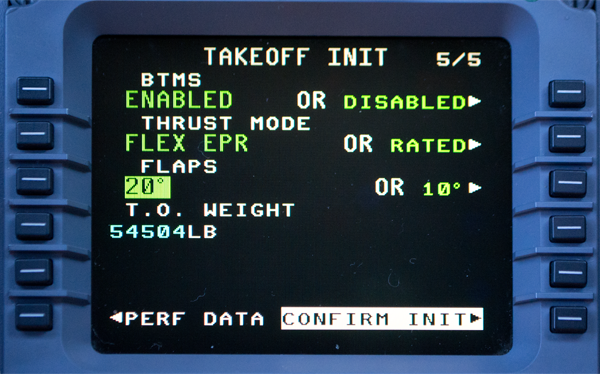
Photo: MCDU Takeoff Init Page 5
Select the next page by pressing the NEXT key.
[G450 Aircraft Operating Manual, §2B-26-50, ¶3.A.]
1L and 1R — The BTMS configuration is displayed at this line. When ENABLED, brake temperature computations are used in computing the TAKEOFF DATA. When DISABLED brake temperature computations are not used in computing the TAKEOFF DATA. The default is ENABLED. Should the FMS not be able to perform brake temperature monitoring computations, ENABLED is displayed in inverse video.
If the ENABLED appears in inverse video it may be that the BTMS lost the time and date of the previous braking effort. (The peak temperature for one or more of your brakes will be dashed out in the 1/6 brakes page.) As long as you are sure the brakes are sufficiently cool for the takeoff, you can disable the BTMS. They will record the subsequent peak brake temperatures and will re-enable themselves.
2L and 2R — The selected thrust mode for takeoff calculations is displayed at 2L. The default setting is RATED EPR. Select 2R to change the setting. RATED EPR is defined in the AFM as using full takeoff thrust. The FMS calculates takeoff data for the available field length based on the takeoff EPR rating and V1 between V1MAX and V1MIN on the TAKEOFF DATA pages. FLEX is defined in the AFM as reduced takeoff thrust. This power setting is calculated observing all the limitations in the AFM. The FMS calculates takeoff data for the available field length based on reducing EPR as much as possible (but not more than 0.154 EPR less than RATED EPR, and not less than 1.39 EPR). The pilot can select any V1 between V1MAX and V1MIN on the TAKEOFF DATA pages.
3L and 3R — The selected flap setting for takeoff calculations is displayed at 3L. The default setting is 20_. The setting can be changed at 3R. If the actual flap setting is different than the selected setting, this line is displayed in inverse video.
4L — The takeoff gross weight is displayed on this line. The takeoff weight is the gross weight from PERF INIT page 5. An overriding manual entry is permitted on this page. The default takeoff weight can be restored by entering *DELETE*. If the PERF INIT weights have not been entered, the T.O. WEIGHT line displays a prompt. If the weight changes during ground operations, the takeoff data is automatically calculated using the new weight unless a weight has been manually entered.
6R — The CONFIRM INIT prompt is displayed when all required takeoff initialization items are entered. The CONFIRM INIT prompt must be selected to start takeoff data calculation. Changes made to takeoff initialization after selection of the CONFIRM INIT prompt are automatically recalculated without selecting CONFIRM INIT. In other words, selection of the CONFIRM INIT prompt is only required for initial calculation.

Photo: MCDU Takeoff Data Page 1
If the takeoff initialization was successful, the Takeoff Data page will be displayed next.
Takeoff Data: Distances
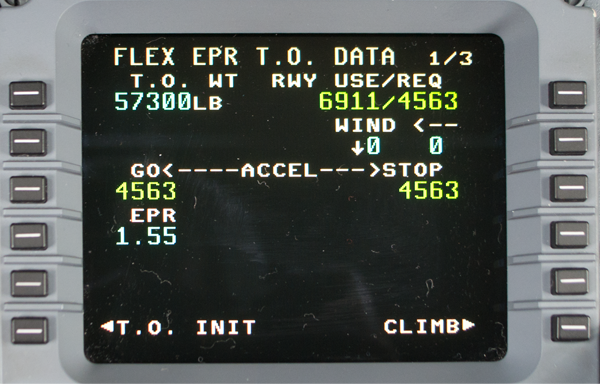
Photo: MCDU Takeoff Data, Page 1
[G450 Aircraft Operating Manual, §2B-26-50, ¶3.B.]
The page title includes the selected thrust mode.
To change the thrust mode, select T.O. INIT (LSK 6L).
Projected takeoff weight (1L)
This number is taken from the Performance Init 5/5 page.
Usable runway length (runway length minus displaced threshold) / AFM takeoff distance (1R)
The runway length comes from Takeoff Init 2/5 page, the runway required should be the greater of the accelerate-go and accelerate-stop distances given on line 3. In the example we have a balanced field condition.
Maximum takeoff weight for current configuration (2L)
I have not seen this line in our G450.
Takeoff runway wind condition (2R).
This is a component breakdown from the wind entered at Takeoff Init 2/5.
Accelerate-go and accelerate-stop distances (3L and 3R)
These two numbers come from the performance computer's computation of takeoff data which is based on the AFM. You can impact both by changing V1. More about this below.
Takeoff EPR (4L).
Accelerate-Go and Accelerate Stop Explained
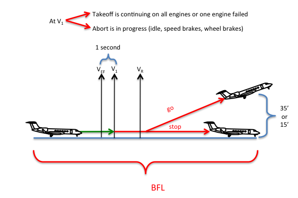
Figure: V1 Abort or Go,
[G450 Airplane Flight Manual, §5.1]
ACCELERATE-GO DISTANCE - the required distance to accelerate with both engines operating to the critical engine failure speed, sustain an engine failure, and continue the takeoff to a height of 35 feet AAL on a dry runway or 15 feet AAL on a wet runway.
ACCELERATE-STOP DISTANCE - the required distance to accelerate to V1, initiate actions to abort the takeoff, and come to a complete stop.
V1, TAKEOFF DECISION SPEED - the speed from which a decision to continue the takeoff results in a takeoff distance that will not exceed the available accelerate-go distance, or from which a decision and action to bring the airplane to a full stop will not exceed the accelerate-stop distance available. In the event of an engine failure, this speed takes account of the pilot recognition and reaction time of 1.0 seconds, including the pilot's first action after recognizing the engine failure. For an all-engine rejected takeoff, this is the speed at which the pilot performs his first action to abort.
The label "Decision Speed" is a bit misleading. The decision must have been made and the action to abort or continue must have been made by V1.
More about this: V1 - Decision Action Speed.
VEF, CRITICAL ENGINE FAILURE SPEED - the airspeed at which either engine fails.
Takeoff Data: V1
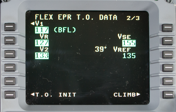
Photo: MCDU Takeoff Data, Page 2
Unlike previous Gulfstreams, the G450 performance computer defaults to a balanced field length. You can change that by selecting V1 (LSK 1L). Why would you want something other than BFL?
An Obstacle Rich Environment — If you've loaded the airplane to the point where you just barely make all climb restrictions, you may prefer to abort the takeoff if possible. Selecting V1MAX makes it more likely you will abort if an engine fails during takeoff, and if you lose an engine after this higher V1, you will have more speed to be beat those obstacles.
A Contaminated, Short Runway — If an aborted takeoff will require everything to work perfectly to get you stopped on the runway, you may prefer to take the airplane in the air and circle back to land with all of the runway in front of you. If so, selecting V1MIN makes it more likely you will be in "go mode" after an engine failure.
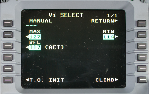
Photo: MCDU V1 Select Page
[G450 Aircraft Operating Manual, §2B-26-50, ¶3.B.]
The default value is V1BFL
1L — This line displays the manually entered V1 speed. Any entry between MAX and MIN can be entered.
2L and 2R — The MAX and MIN values of V1 are displayed. Selection can be made at either 2L or 2R.
3L — The BFL V1 speed is displayed. This is the V1 speed at which the accelerate-go and accelerate-stop distances are equal. If V1BFL cannot be computed for the data entered on the TAKEOFF INIT pages, the line is blank. The default V1 is either V1MAX or V1MIN, whichever is closer to BFL.
Takeoff Data: Climb Performance
Minimum Level-Off Height Explained
[G450 Airplane Flight Manual, §5.6] The minimum level-off height is 1500 feet AAL. When multiple obstacles exist in the takeoff profile, the highest obstacle will dictate the minimum level-off height even if this is not the most demanding obstacle from a required gradient standpoint. If the horizontal distance is more than 120,000 feet from Reference Zero, the recommended level-off altitude must be determined as the sum of the obstacle height above Reference Zero plus the product of .008 times the horizontal distance from Reference Zero.
The performance computer does the math for you, so long as you only have three obstacles to enter. With more than three, you can either do the math for each or enter each in turn until you get the most restrictive answer.
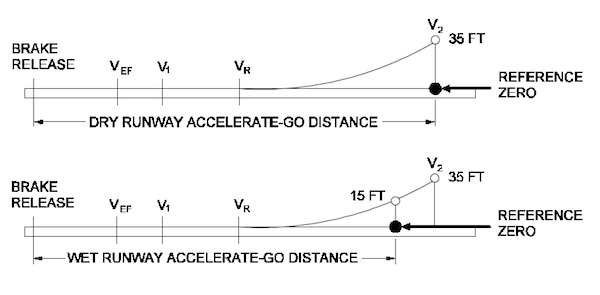
Figure: Reference Zero, from G450 Airplane Flight Manual, §5.1.
[G450 Airplane Flight Manual, §5.1] REFERENCE ZERO - a point on the runway or clear way plane at the end of the accelerate-go distance that is used as the reference point for an obstacle clearance analysis.
The 15 versus 35 foot height at reference zero is mandated by 14 CFR 25, §25.113 but is really insignificant for this discussion. What really matters is that it is measured at the end of the accelerate-go distance and could very well be thousands of feet before the departure end of the runway.
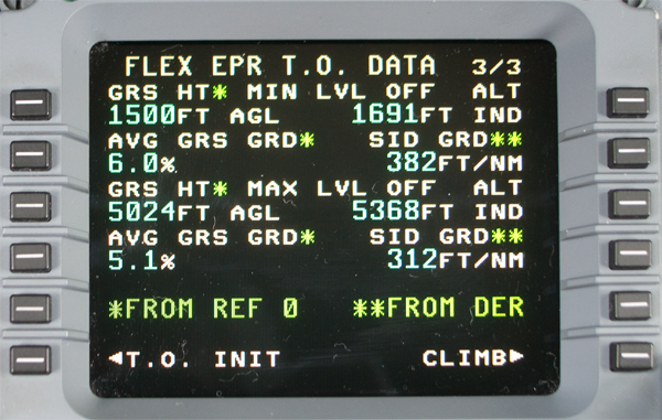
Photo: MCDU Takeoff Data Example, Page 3
This can be a particularly misleading chart because of the green "*FROM REF 0" and "**FROM DER" line which leads you to believe the page is best understood as a left side and a right side, which is not true. It is best understood as a top half (MIN LVL OFF) and a bottom half (MAX LVL OFF). So that's how we'll cover it...

Photo: MCDU Takeoff Data Example, Page 3, Top Half Only,
[G450 Aircraft Operating Manual, §2B-26-50, ¶3.B.]
1L — The minimum gross Level-Off height from reference zero is displayed here.
Without an obstacle, this is usually, 1500' AGL. With an obstacle, it is usually, but not always, equal to the height of the obstacle.
1R — The minimum Level-Off altitude (altimeter indicated) is displayed here.
This is the same as figure at 1L adjusted for the elevation of the departure end of the runway and ISA temperature conditions. In the example there is no obstacle, the departure end of the runway is at 124', and the temperature is 2°C which results in a temperature correction for 1,500' of 67'. (So 1,500 + 124 + 67 = 1,691')
A key point to understand is that both LSK 1L and LSK 1R are the same point in space.
2L — The minimum gross gradient from reference zero is displayed here.
This gradient averages the curve of the airplane as it starts from 35' above the runway to the point referred to at LSK 1L, 15' if the runway is wet.
2R — The minimum SID gross gradient from DER is displayed here.
This gradient is the line from the departure end of the runway to the point referred to at LSK 1R.
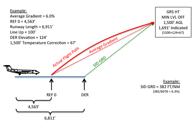
Figure: Min Level Off Example
In our example, the aircraft arrives at its 1,500' AGL point (LSK 1L) via a curved arc as the single engine performance tapers off a bit with altitude. The average gradient of that arc comes to 6.0% (LSK 2L). The performance computer tells us that this point in space will be at 1,691' indicated altitude (LSK 1R), based on the departure end of the runway's elevation and the temperature correction off ISA. It is the exact same point in space. The performance computer draws a line from the departure end of the runway to this point and tell us it comes to 382 ft/nm (LSK 2R), which factors to a gradient of 6.3%. It makes sense that this would be a steeper gradient than LSK 2L, given it starts later and ends at the same point.
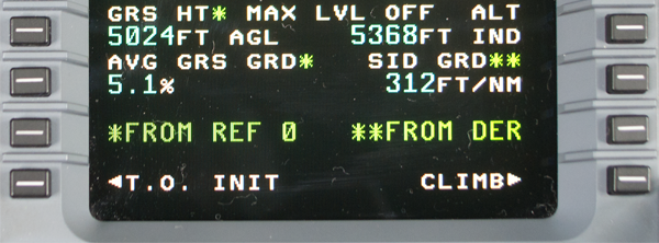
Photo: MCDU Takeoff Data Example, Page 3, Bottom Half Only,
[G450 Aircraft Operating Manual, §2B-26-50, ¶3.B.]
3L — The maximum gross Level-Off height from reference zero is displayed here. This value is based on a 10-minute limit on the use of takeoff thrust for single engine operation.
This is nothing more than the original scenario continued beyond the minimum level off height to the point where the operating engine reaches its ten minute limit. The height is measured 35' (dry runway) / 15' (wet runway) above the runway, "reference zero."
3R — The maximum Level-Off altitude (altimeter indicated) is displayed here.
Once again this is the same point in space, adjusted for the elevation of the departure end of the runway and corrected for non-standard ISA temperature. In the example there is no obstacle, the departure end of the runway is at 124', and the temperature is 2°C which results in a temperature correction for 5,000' of 220'. (So 5,024 + 124 + 220 = 5,368')
More about: Altimeter Temperature Correction.
4L — The average gross gradient from reference zero is displayed here.
The aircraft flies an even shallower arc and in the example the average of that arc comes to 5.1%.
4R — The maximum SID gross gradient from DER is displayed here.
The performance computer draws a line from the departure end of the runway to the point in space where the engines reach their 10 minute limit.
5L — From reference zero, note - an * indicates that the data is computed from the Reference Zero position on the runway.
5R — From DER, note -- ** indicates that the data is computed from the departure end of the runway (DER).
6L — T.O. INIT prompt.
6R — CLIMB prompt.

Figure: Max Level Off Example
In our example, the aircraft arrives at then ten-minute point when at 5,024' AGL (LSK 1L) via a curved arc as the single engine performance tapers off a bit with altitude. The average gradient of that arc comes to 5.1% (LSK 2L). The performance computer tells us that this point in space will be at 5,368' indicated altitude (LSK 1R), based on the departure end of the runway's elevation and the temperature correction off ISA. It is the exact same point in space. The performance computer draws a line from the departure end of the runway to this point and tell us it comes to 312 ft/nm (LSK 2R), which factors to a gradient of 5.1%. It makes sense that this would be close to the average gradient. The further away you get from takeoff, the less significant the distance between reference zero and the departure end of the runway to become.