What does that triangle mean again?
PlaneView and Symmetry are incredible avionics suites. As you gain experience you find your awareness expanding. You begin noticing things that you hadn’t noticed before. One such feature for me was the “Heading Triangle.”
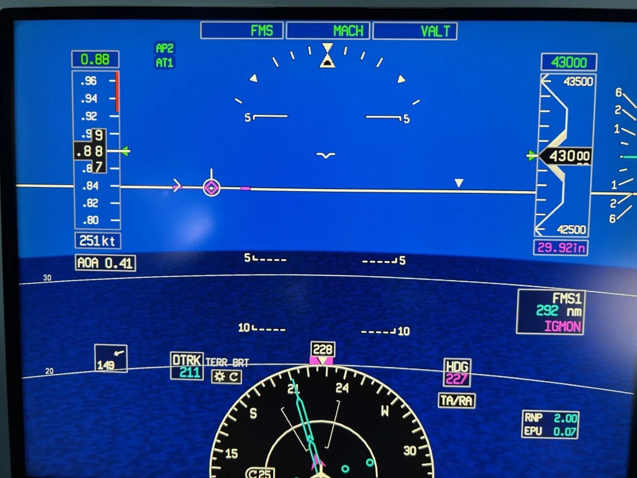
Before getting ahead of ourselves, let’s point out features of the PFD that come into play for this discussion:

Heading Triangle - indicates the heading of the aircraft in relation to the SV-PFD, when in Heading Plus Mode. *Note: the term “Heading Plus Mode” does not exist in either the PlaneView or Symmetry Manuals. The term is used in a couple articles that discuss the Heading Triangle feature. More on this later.
Boresight - represents the nose of the aircraft. It tells you where the nose of the aircraft is pointed…or so we thought! Read on to discover when it does not.
Flight Path Marker (FPM) - represents the aircraft flight path. It tells you where the aircraft is going. Note: the terms Flight Path Marker (FPM) and Flight Path Vector (FPV) are often interchanged. I will primarily use FPM for consistency.
View Frustum - depicts the area being viewed as Synthetic Vision. Spoiler alert: the View Frustum shifts left and/or right as necessary “to keep the proper relationship of the FPM to terrain.” More on this later.
Wind Display - displays the wind direction and strength.
Ok, with that introduction out of the way, let’s take a look at the information provided by Gulfstream on “the triangle.”

A search of PlaneBook reveals only one page with information regarding the “Heading Triangle,”
Symmetry Flight Deck Manual, page 207:
Let’s break that down to ensure we understand what it is saying:

“The SV-PFD uses a heading-up perspective line-of-sight mode for positioning the terrain image on the display until the flight path marker (FPM) reaches the left or right limit….”
As long as the FPM has not reached its outer limit the SV-PFD is in this mode. In this mode the boresight directly corresponds with the heading of the aircraft in relation to the terrain displayed on the SV-PFD.

“…When the FPM reaches the lateral display limit, the FPM stays there and the terrain views are shifted to keep the proper relationship of the FPM to terrain. This is indicated by the heading triangle.”
“…The heading triangle moves laterally above the zero-pitch line in relation to aircraft heading…”
This mode is known as “Heading Plus Mode,” as you will see later. In this mode the boresight no longer directly corresponds with the aircraft heading. Hence the “Heading Triangle” - it now represents the heading of the aircraft on the SV-PFD.
Further research online revealed a couple articles that mention Heading Plus Mode. I thought compiling them here would beneficial.
From Flying Magazine, SVS Another Safety First for Gulfstream, by J. Mac McClellan - March 2008:
…Gulfstream developed a ‘heading plus’ mode where the flight path marker moves out to the edge, and a small triangle appears on the horizon line showing you the actual crab angle…This mode is unique to Gulfstream and is one of many problems it solved to show heading up on the SV image, while still making sense of track….

Let’s make sure we understand what is being said:
“…a small triangle appears on the horizon line showing you the actual crab angle…”
As you know, Crab Angle is the angle formed between the direction an aircraft is pointed and the direction it is tracking over the ground, resulting from a crosswind component.
In Heading Plus Mode the direction the aircraft is pointed (heading) is not the Boresight. In relation to the depicted terrain, the direction the aircraft is pointed is the Heading Triangle.

At the risk of being redundant, I’ll restate it another way:
The boresight is always displayed in the middle of the SV-PFD, as depicted in this figure. When the PFD changes from the Heading-Up Perspective Line-of-Sight Mode to the Heading Plus Mode the boresight no longer corresponds with the aircraft heading as displayed on the SV-PFD. In Heading Plus Mode the Heading Triangle depicts the aircraft heading on the zero-pitch line of the SV-PFD.
*A note about the boresight, from James Albright: “I think it is important to note that the boresight is always where the nose is in relation to the bank angle indicator above, but may not correspond to the terrain below because the terrain skews according to the frustum. The heading triangle, on the other hand, only applies to the terrain below according to the frustum. In an unusual attitude situation, the boresight reins supreme.”
From AIN Online, Gulfstream crosses SVS finish line, by Stephen Pope - February 27, 2008:
…The normal SVS layout features a wide zero-pitch reference line flanked by transparent airspeed and altitude tapes. A flight-path marker and speed chevron on the display mimic the symbology that’s shown on the HUD, with an additional v-shaped marker always showing where the nose is pointed. A bumpy, 54-knot crosswind on the Rnav approach to Mount Snow’s Runway 1 was more than adequate to demonstrate one of the more noteworthy advanced features of SV-PFD, called heading-plus mode. When crosswinds are strong, the display automatically reverts to this mode, whereby the visual scene shifts to the left or right by as much as 40 degrees so that the divergent flight-path marker and an inverted v marker are always shown on the display together.
“We actually shift the world to keep the flight-path marker conformal to the view outside,” explained Horn. The technique lets the pilots always see the runway as well as where the nose is really pointed, even when there is a wide disagreement between the two. It’s a hard concept to visualize without actually seeing it demonstrated in the real airplane or a simulator, but once the shifted scene is presented on the display on a real flight it is quite easy for the pilot to interpret the information. One of the biggest benefits the shifted scene provides is letting the pilots know exactly where they should be looking for the runway when they break out of the clouds….

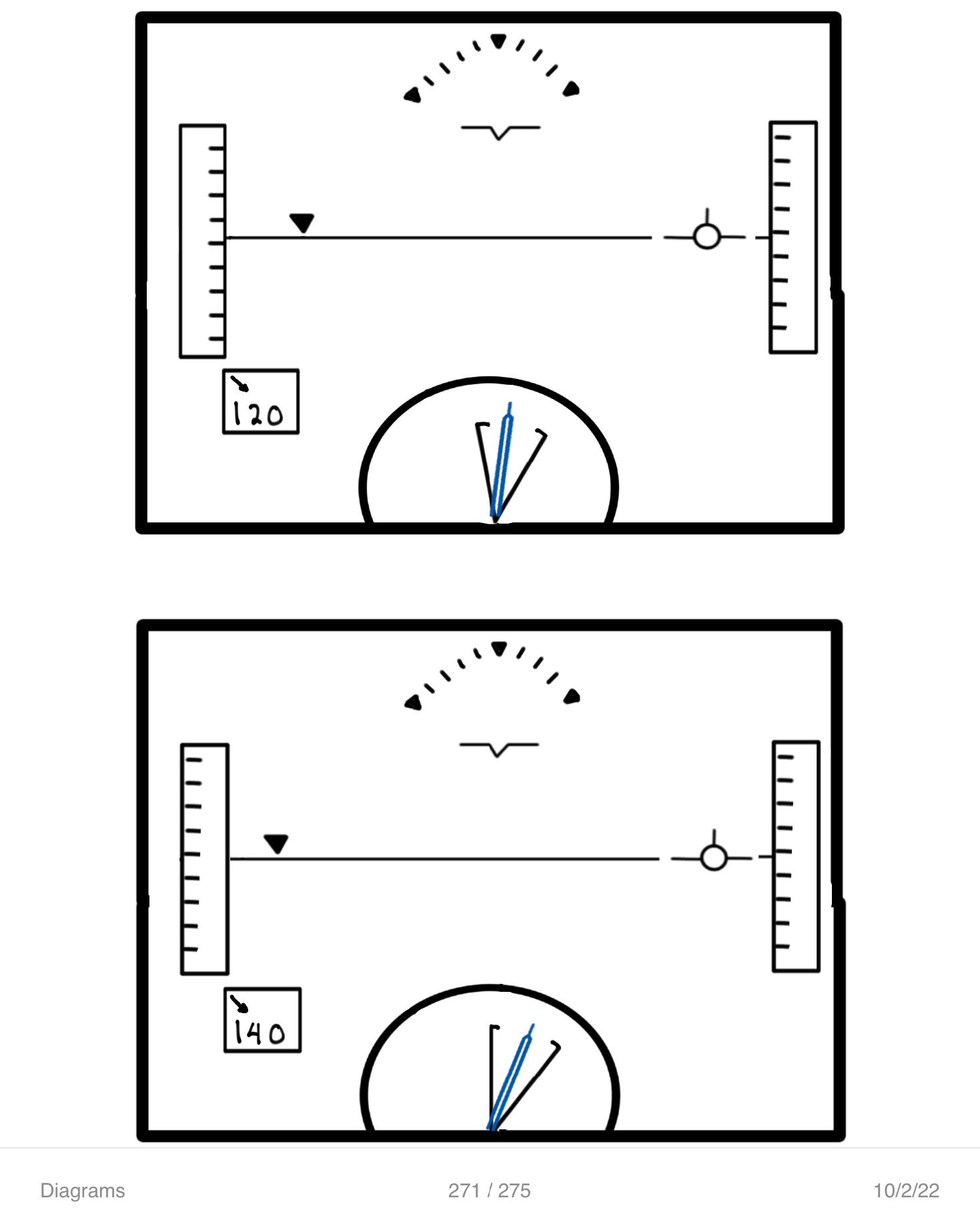
In this picture the Heading Triangle is beginning to fade in with about an 80 kt right crosswind. Notice the View Frustum has shifted slightly left - G650ER, Uncaged, Full PFD.
Photo by Ivan Luciani
Here, the Heading Triangle is full bright and far to the right due to the strong (nearly 150 kt) right crosswind - G650ER, Uncaged, Full PFD. Notice the View Frustum is pointed further left than in the picture above.
Photo by Ivan Luciani
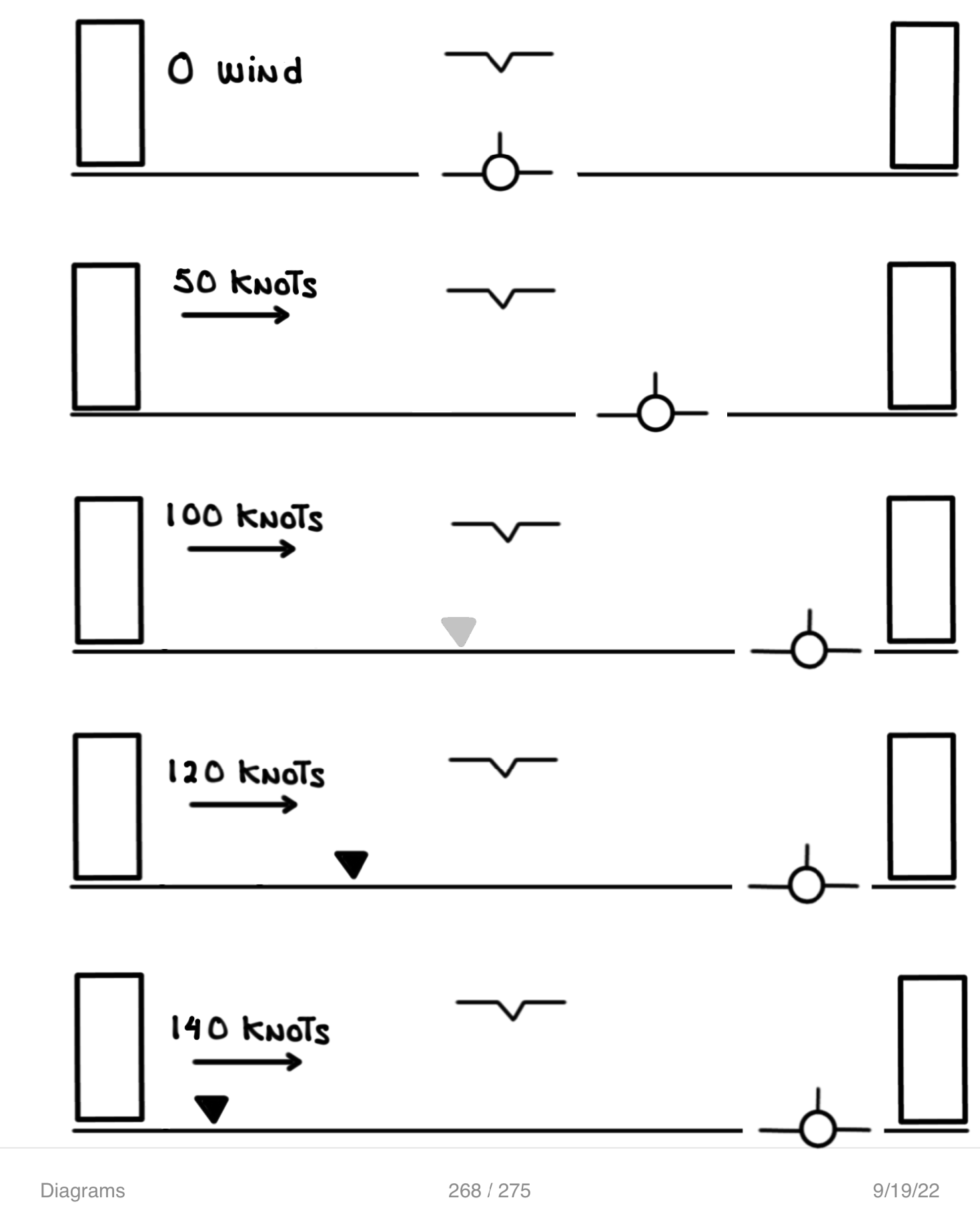
In this diagram the Flight Path Marker (FPM) is sliding right as the left crosswind increases.
Eventually the FPM reaches the far right limit of the PFD.
As the crosswind continues to increase the Heading Triangle begins to appear. The Heading Triangle slides left as the aircraft crabs further left into the increasing crosswind.
Graphic by Ivan Luciani
The further outward the Heading Triangle slides (left, in this case) the further the View Frustum compensates (shifting right) to keep the FPM conformal with the outside view.
Graphic by Ivan Luciani
So, putting it all together:
As the crosswind increases the FPM eventually reaches its outer limit.
When the FPM reaches its outer limit the View Frustum deflects, as necessary, towards the FPM to keep the proper relationship of FPM to terrain.
When the View Frustum begins to deflect towards the FPM the Heading Triangle appears on the zero-pitch line as an indication that the SV-PFD is in Heading Plus Mode. In this mode the boresight no longer corresponds with the aircraft heading in relation to the depicted terrain; the Heading Triangle does.

So, how do these two modes compare to each other? Here are a few examples:


What about the HUD? I’m glad you asked! Unlike the SV-PFD, the HUD does not have a Heading Plus Mode. The HUD Boresight will always be the heading of the aircraft. If the HUD’s FPV were to reach a lateral limit, either by other symbology or by the display field-of-view, the FPV would flash indicating that the Flight Path is no longer conformal with the real-world scene.

Here is a representative HUD overlay of the SV-PFD. As you can see, the HUD’s FPV and PFD’s FPM both indicate the same path.
However, notice that the HUD’s Boresight and SV-PFD’s Boresight are not coincident. The HUD’s Boresight is over the SV-PFD’s Heading Triangle.
So why the difference between the PFD and HUD?
Again, from the AIN Online article:
…the display mimic the symbology that’s shown on the HUD, with an additional v-shaped marker always showing where the nose is pointed…We actually shift the world to keep the flight-path marker conformal to the view outside…The technique lets the pilots always see the runway as well as where the nose is really pointed, even when there is a wide disagreement between the two….One of the biggest benefits the shifted scene provides is letting the pilots know exactly where they should be looking for the runway when they break out of the clouds….
“You lost me at ‘View Frustum!’”
Don’t worry, I haven’t forgotten about you. Here is a quick “Frustum” refresher, just for you:

The frustum depiction on the HSI represents the viewed area of the SV PFD.
Bonus points: you’ll see both “Frustum” and “Frustrum” used. I believe “Frustum” is correct.
Symmetry Flight Deck Manual, page 253
For a more in-depth understanding of the term “View Frustum” it’s helpful to review Honeywell’s Apparatus and method for displaying a synthetic vision system view direction patent application:
The term “view frustum”…means a frustum that is a truncated pyramid of what is in view. Objects within the frustum appear on the screen. The eye, or camera, is at the tip of the pyramid. The pyramid extends out along the direction the eye is looking.
When a SVS image is displayed on the Primary Flight Display (PFD) and the SVS view may be centered at an angle other than the heading, the pilot needs to be able to quickly correlate the displayed SVS view to information in the compass….One known means involves drawing lines (frustum lines) on the compass from the aircraft symbol, or close to it, toward the edge of the compass's outer ring. This method works well to show the relationship of content inside the compass, especially lateral terrain and the flight path...it is desirable to provide a display system and method allowing the pilot to quickly correlate the content of the SVS display for comparing the view ahead of the aircraft to the aircraft's heading and discern the differences when path and heading are sufficiently different.
Also, from Honeywell’s Handheld Synthetic Vision Device patent application:
The content of a scene for a given view point depends on what actual or digitally created objects fall within the view frustum corresponding to the selected viewpoint. The view frustum is the volume bounded by the angular extent of the field of view and by minimum and maximum distances….The frustum is a mathematical construct that is used in deciding which objects from a graphics database should be drawn on a display. Briefly, a database is culled for objects that lie within or partly within a frustum. Objects that lie at least partly within the frustum are rendered on the display in proper perspective according to the direction from which they are viewed.
And, if you want to go even deeper, here’s what wikipedia has on the matter:
In 3D computer graphics, the view frustum (also called viewing frustum) is the region of space in the modeled world that may appear on the screen; it is the field of view of a perspective virtual camera system.
The view frustum is typically obtained by taking a frustum—that is a truncation with parallel planes—of the pyramid of vision, which is the adaptation of (idealized) cone of vision that a camera or eye would have to the rectangular viewports typically used in computer graphics. Some authors use pyramid of vision as a synonym for view frustum itself, i.e. consider it truncated.
The exact shape of this region varies depending on what kind of camera lens is being simulated, but typically it is a frustum of a rectangular pyramid (hence the name). The planes that cut the frustum perpendicular to the viewing direction are called the near plane and the far plane. Objects closer to the camera than the near plane or beyond the far plane are not drawn. Sometimes, the far plane is placed infinitely far away from the camera so all objects within the frustum are drawn regardless of their distance from the camera.
Viewing-frustum culling is the process of removing from the rendering process those objects that lie completely outside the viewing frustum. Rendering these objects would be a waste of resources since they are not directly visible. To make culling fast, it is usually done using bounding volumes surrounding the objects rather than the objects themselves.
There you have it. You now have a “down in the weeds” understanding of the Heading Triangle and the View Frustum. Congratulations.